DNA/DNR-429-512/566 ARINC 429 Layer
Chapter 1
9
Introduction
Tel: 508-921-4600
www.ueidaq.com
Vers:
4.5
Date: December 2013
DNx-429-Chap1x.fm
© Copyright 2013
United Electronic Industries, Inc.
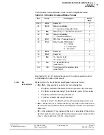
The table below illustrates the differences in bit numbering for various protocols.
Table 1-2. Differences in Bit Numbering for Various Protocols
Holt
Bit No.
DNA
Bit No.
ARINC
Standard
Bit No.
Name
Description
15
Word
2
31
29
SIGN
Sign Bit
14-0
30-16
28-14
DATA
15 main data bits
15-13 Word
1
15-13
13-11
DATA
3 additional data bits
12-11
12-11
10-9
SDI
Source/Destination Identifier,
2-bit field used as an additional
filter, programmed by a direct
write to the HI-3282 configur-
ation word and a write to the
AR566_ARDA0
register.
10-9
10-9
31-30
SSM
Sign/Status matrix or data bits.
See ARINC-429 protocol
documentation for details.
8
8
32
PARITY
Parity bit – auto inserted by the
transmitter and calculated by
the receiver. Normal parity for
the ARINC-429 is “odd”. (Parity
bit should be set if the number
of “1”s in the rest of the bits is
even, and should be cleared if
not.) DNA-429 layers support
even, odd, or no parity modes
(the ARINC standard is “odd”
parity). In “no parity” mode, the
PARITY bit is transmitted to the
bus, but is ignored.
7
7
1
LABEL
Label — This bit is used to
identify data types and
associated parameters. DNA-
429 layers have a very flexible
acceptance filter with an option
to put only “new” data into the
FIFO or to trigger the Scheduler
when the selected label is
received.
When SDI bits are enabled, the
Label Filter functions as a 10-bit
identifier.
6
6
2
5
5
3
4
4
4
3
3
5
2
2
6
1
1
7
0
0
8


