DNA/DNR-429-512/566 ARINC 429 Layer
Chapter 1
15
Introduction
Tel: 508-921-4600
www.ueidaq.com
Vers:
4.5
Date: December 2013
DNx-429-Chap1x.fm
© Copyright 2013
United Electronic Industries, Inc.
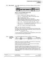
The Scheduler Command/status Format is shown in
Figure 1-4
below.
Note that bits 31:22, 19,18 should be reset to 0 for correct operation and for
compatibility with future enhancements.
1.8.5.1
Bit
Descriptions
Bit Descriptions for the Scheduler (see
Figure 1-4
) are as follows:
•
PS1, PS0
– Prescaler/clock selector and entry disable flag
•
00 (0)Entry disabled. Disabled entries are ignored by the Scheduler
•
01 (1)Entry enabled and using 100uS clock as source for time delay
•
10 (2)Entry disabled and using Prescaler 0
•
11 (3)Entry enabled and using Prescaler 1
•
If entry is “slave”, this field should match corresponding master entry
•
MA
— “Master” Bit. If set, indicates that entry is a “master” and when sched-
uled for output should also schedule all related slave entries for output at the
same time.
•
RC
— Recyclable Bit. If set, indicates that entry is recyclable. When sched-
uled for output, the internal value for the time delay counter is cleared and the
entry is output again when the time delay expires.
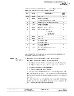
Table 1-4. Scheduler Command/Status Format
Bit Name
Description
Reset
State
31-25
RSV
Reserved
0
24
ECO
Status only,
sticky
,
=1 - Execution Completed Once
0
23
ME
Status-only, =1 - Marked for execution
0
22
EO
Status only,
sticky
,
=1 - Execution Overrun
0
21
PS1
PS1,PS0 - Prescaler Source/
Entry Disable: 00-Disabled
01 - 100 uS
10 - Prescaler 0
11 - Prescaler 1
0
20
PS0
0
19
RSV
Reserved
0
18
RSV
Reserved
0
17
MA
=1 – Master Entry
=0 – Slave entry
16
RC
=1 –Recyclable Entry
(valid if MA=1)
0
15-0
TD
Time Delay for the selected clock
(valid if MA=1)
0


