DNA/DNR-429-512/566 ARINC 429 Layer
Chapter 1
18
Introduction
Tel: 508-921-4600
www.ueidaq.com
Vers:
4.5
Date: December 2013
DNx-429-Chap1x.fm
© Copyright 2013
United Electronic Industries, Inc.
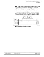
Figure 1-8
shows an example of how to wire the ARINC-429 bus in a multi-drop
network configuration (which is the most common) with the DNx-429-5xx.
In
Figure 1-8
, the DNX-429-566’s Channel0 is acting as the master transmitter
and all other devices are slaves (receiving only). The physical medium between
master and slave(s) is two twisted-pair wires carrying a differential signal:
•
a
is for the non-inverting signal (may be inaccurately labelled as +)
•
b
is for the inverting signal (may also be inaccurately labelled as -)
The signals from a/b lines are with reference to the ground. Even though the
configuration in
Figure 1-8
is common, other configurations are also possible.
Figure 1-8. Wiring for a ARINC-429 network
DNx-429-566 Layer
Channel 0
Tx-A-0
Tx-B-0
Rx-A-0
Rx-B-0
GND
Rx
Tx
Slave 1
Rx
Tx
Slave 2...
Slave n
A
B
GND
TxD
RxD
Data(A)
Data(B)
A B
A B

