Unipower Sageon II Скачать руководство пользователя страница 23

Installation 


Sageon II Bulk Product Manual 


PM990-5201-00, Issue 6 

3-9  


3.8


CONTROLLER POWER CONNECTIONS 

Power for the Controller and its peripherals is derived from the DC bus.  No additional user connections are required to 
power the Controller or provide system voltage regulation. 

3.9


FRONT PANEL USB COMMUNICATIONS CONNECTION 

The front USB port on the Controller is configured as USB-slave and has a B-type connector.  A standard USB A-to-B cable 
is required.  The Controller can only communicate via the USB port to a PC running the Sageview software. 
 
The USB connection requires that a USB driver be installed on the PC. The first time the Controller is plugged into the PC 
via the USB port, a Microsoft® Windows dialogue box will appear asking the user to install the Controller USB Interface 
drivers. The Microsoft® Windows operating system should be able to find the drivers automatically on the Sageview CD-
ROM, assuming it is in the CD-ROM drive of the PC.  
 
If Sageview is running when the unit is plugged in, a Windows dialogue box will appear asking the user if they wish to 
connect to the unit immediately. Otherwise, the user will need to select the Controller from the available controller USB 
devices in USB section in the Connection Setup. 

3.10


REMOTE COMMUNICATION CONNECTION 

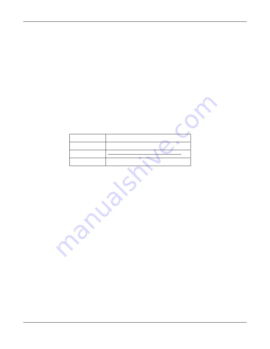
The optional remote communications modules can be one of the following: 
 

P/N Description 


103.4014.00


TCP/IP Interface Card 


103.4015.00  

Ethernet TCP/IP Interface Card w/SNMP 

{Superseded by 103.4036.00 

103.4036.00 

Ethernet TCP/IP Interface Card w/SNMP v3 


The following sections describe the interfaces in more detail and cover some of the set up requirements for the more 
advanced interfaces. 


Due to the slow data rate (9600bps), termination of the line with resistors generally is not required. However, if high rate of 
data corruption is experienced (slow data update in monitoring program), line termination resistors should be installed at both 
ends of the network. The value of the resistors depends on the gauge of the twisted pair and should be equal (or closest) to 
line characteristic impedance. I.e. for a twisted pair of 24AWG wires characteristic impedance of 100ohm – use a 100-ohm 
resistor. 

3.10.1


TCP/IP and Sageview Interfaces 

The interface is a 10/100BASE-T Ethernet adaptor. The TCP/IP port sends Controller data over a network to a PC running 
Sageview control and monitoring software.  The Sageview interface provides this function for up to 2 PCs on the network 
simultaneously as well as providing SNMP traps on alarms, system time synchronization to a global clock if access to the 
internet is available, and a simplified system status Webpage (HTTP).  Both units have the same footprint and connections.  
If direct connection to a PC network port is required, a crossover network cable should be used.  To set up Sageview, follow 
the instructions on the installation CD. 
 
To enable network access on the TCP/IP port, an IP address must be assigned to the port. If access over the Internet is 
considered, the gateway address must be programmed as well. There are several methods to do that, two are recommended 
and are described in Appendix A.  Other operating parameters of the interface are pre-programmed and should not be 
changed. 
  
To be able to assign a network address, the Ethernet address (referred to also as hardware address or MAC ID) of the 
interface must be known. A small label indicating the MAC ID similar to one shown below. The factory default IP address is 
192.168.10.251. 
 

Note: The interface IP address cannot be changed until the Power Module has been commissioned and the Controller is 
operational. 

Содержание Sageon II

Страница 1: ...nual PM 990 5201 00 Issue 6 sageon2_48 man pdf UNIPOWER LLC 3900 Coral Ridge Drive Coral Springs FL 33065 United States Tel 954 346 2442 Fax 954 340 7901 Email customer services unipowerco com Web sit...

Страница 2: ......

Страница 3: ...of shipment open the container and inspect the contents for damage If it is necessary to move or otherwise handle the shipment refer to the next section Handling for instructions and warnings Unpack t...

Страница 4: ...wn in italic in the label drawing below in all correspondence with UNIPOWER A sample nameplate is shown below 225 8001 00 SAGEON II POWER MODULE PART NUMBER 110 5201 INPUT RATING 85 300VAC 18A max 45...

Страница 5: ...bited Copyright UNIPOWER LLC 2015 DISCLAIMER Data descriptions and specifications presented herein are subject to revision by UNIPOWER LLC without notice While such information is believed to be accur...

Страница 6: ...ANSION MODULES 3 10 4 COMMISSIONING 4 1 5 OPERATION 5 1 5 1 SUMMARY OF CONTROLLER FRONT PANEL CONTROLS 5 1 5 2 CONTROLLER COMPONENTS 5 1 5 2 1 Alpha numeric Display 5 1 5 2 2 Front Panel Pushbuttons 5...

Страница 7: ...board connections 2 4 Figure 3 1 Mount points for securing Power Module in a rack 3 1 Figure 3 2 AC Feed Terminations 3 2 Figure 3 3 Single Phase feed phase to neutral 3 3 Figure 3 4 Single Phase fee...

Страница 8: ......

Страница 9: ...ivalent standard For open rack use the back of the magazine must be fully enclosed by its covers and the AC wiring terminations must be protected by either a grounded casing or an enclosure that provi...

Страница 10: ......

Страница 11: ...sed The Power Module provides the following integrated features Bulk power N 1 redundant rectifiers battery charge current limiting opt short circuit and reverse polarity protection battery temperatur...

Страница 12: ...Configuration Sageon II Bulk Product Manual PM990 5201 00 Issue 6 2 2 Figure 2 3 400A Bulk Power with AC Breakers Figure 2 4 600A Bulk Power with AC Breakers...

Страница 13: ...ribbon 7 Standalone system voltage connection Controller power and voltage sensing 8 Load circuit breaker trip detection circuitry connection Notes Devices and cable connections are pre wired as part...

Страница 14: ...Figure 2 7 Alarm relay board connections The alarm relay board is installed on the side of the Power module such that Relay 5 is on the top when viewed from the rear of the metalwork Each alarm is us...

Страница 15: ...ilarly the energy hazard associated with the batteries connected to the DC bus must be addressed with appropriately insulated tools and other measures to prevent accidental short circuits to the DC bu...

Страница 16: ...feed is individually protected and the installer is only required to connect a single AC supply 1 phase to the AC DIN rail terminations 3 3 MAINS CONNECTIONS Figure 3 2 AC Feed Terminations 3 3 1 Fac...

Страница 17: ...Installation Sageon II Bulk Product Manual PM990 5201 00 Issue 6 3 3 Figure 3 3 Single Phase feed phase to neutral Figure 3 4 Single Phase feed phase to phase...

Страница 18: ...Installation Sageon II Bulk Product Manual PM990 5201 00 Issue 6 3 4 Figure 3 5 split Single Phase feed phase to neutral Figure 3 6 Y Three Phase feed connected rectifiers phase to phase...

Страница 19: ...Installation Sageon II Bulk Product Manual PM990 5201 00 Issue 6 3 5 Figure 3 7 Y three Phase feed phase to neutral Figure 3 8 three Phase feed phase to phase...

Страница 20: ...tion Sageon II Bulk Product Manual PM990 5201 00 Issue 6 3 6 Figure 3 9 Y three phase feed Single Phase to rectifiers phase to phase Figure 3 10 Y Three Phase Feed Single Phase to Rectifiers phase to...

Страница 21: ...ses Other arrangements for 3 phase Y with similar levels of protection are also possible as shown below The voltage rating of the arrestor should be selected based on the maximum AC voltage likely to...

Страница 22: ...s Locate the ambient sensor close to the intake air zone of the Power Module Locate the battery sensor on a battery block in the middle Module of the battery bank likely hot zone 3 7 AUXILIARY RELAY C...

Страница 23: ...a rate 9600bps termination of the line with resistors generally is not required However if high rate of data corruption is experienced slow data update in monitoring program line termination resistors...

Страница 24: ...All boards are factory wired and allow for easy customer connection access Figure 3 14 AC Option Box Rear View screens removed for clarity 3 12 ADDING AUXILIARY EXPANSION MODULES Modules such as the S...

Страница 25: ...attery charging current limit to 10 of the Ah rating i e if 150Ah battery is used set the limit to 15A this value can be adjusted later to meet your specific charging requirements In many cases these...

Страница 26: ......

Страница 27: ...parameter press ENTER the value will flash on and off To increase the number press INC to decrease the number press DEC When the desired number is on the screen press ENTER again To change parameters...

Страница 28: ...rd must be programmed Once that is done security can be enabled 5 3 1 1 Entering a password to gain access to parameters change When the security function is active any changes to the system settings...

Страница 29: ...act failure A No Demand Control loop in RECTIFIER not in normal state A H S Temp High RECTIFIER heatsink temperature too high where available A Temp Sensor Fail Temp sensor in RECTIFIER faulty S C or...

Страница 30: ...ected or failure A Batt I Limit Battery charging current is being limited to preset value A Bat Sym Alarm Battery discharge currents from battery strings not sharing load equally A Earth Leak Alarm Ea...

Страница 31: ...etup Press ENTER Modify Value up down ENTER to accept Press ENTER to begin flashing display and LEDs Test Indicators Press ENTER ENTER System information including controller software version S N and...

Страница 32: ...Value up down ENTER to accept ENTER Phone 3 0398887788 Modify Value up down ENTER to accept ENTER Phone 3 Cont 2323 Modify Value up down ENTER to accept ENTER Audio Alarm Off INC DEC toggles state EN...

Страница 33: ...4 cells Modify Value up down ENTER to accept ENTER Number of battery banks BCM Batteries 1 Modify Value up down ENTER to accept ENTER Cell Vhi Alarm 2 50V Modify Value up down ENTER to accept ENTER Ce...

Страница 34: ...not be adjusted here Equalise Voltage SMR Default SMR Equalise 56 5V Cannot be adjusted here ENTER SMR voltage above which alarm flagged SMR V high Alarm 57 0V Modify Value up down ENTER to accept ENT...

Страница 35: ...Battery Rating 500Ah Modify Value up down ENTER to accept ENTER Battery Temperature compensation BTC Coeff 3 2 mV C C Modify Value up down ENTER to accept Variable from 0 to 6 0mV C C If BTC not Off...

Страница 36: ...ion EQ Duration 3 hours Modify Value up down ENTER to accept ENTER Periodic equalisation charging trigger EQ Period 12 Weeks Modify Value up down ENTER to accept Set to zero to disable ENTER Manual co...

Страница 37: ...ting to Closed or Auto Power up the rectifiers and reduce the load until the bus voltage increases to the float voltage Load or Battery circuit breaker alarm does not set when the breaker is opened or...

Страница 38: ...A rectifier is indicating RECTIFIER Off or No Response on the Controller RECTIFIER display An AC failure to the rectifier is the most likely cause While the rectifier internal power rails are still a...

Страница 39: ...rical interference where possible EEPROM Fail alarm for the Controller is activated Corrupted data found on the backplane EEPROM that is outside the allowable data range similar to RECTIFIER corruptio...

Страница 40: ......

Страница 41: ...new IP address Select correct network class Click Set IP Address button The process takes several seconds to complete and the progress is indicated below IP address field When completed a dialog box...

Страница 42: ...just press Enter if N press Y followed by enter Next item will be Gateway IP address nnn Enter assigned gateway address then press Enter at each item until set up menu is shown again Terminate Telnet...

Страница 43: ...P address you just set is temporary and will revert to the default value when the unit s power is reset unless you log into the unit and store the changes permanently Refer to the chapter on configura...

Страница 44: ...to the unit basic parameters Hardware Ethernet Autodetect IP addr 192 168 000 098 no gateway set Select 0 and press Enter to configure the Lantronix Interface Server s basic parameters IP Address The...

Страница 45: ...t Can sustain short circuit at output terminals indefinitely Reverse Battery Polarity Internal fuse at output of RECTIFIER High Voltage Shutdown Rectifier shuts down if output exceeds programmed overv...

Отзывы: