GENISYS II System Hardware Installation
UNION SWITCH & SIGNAL
SM-6900B Rev. 0.0
August 1999
3-15
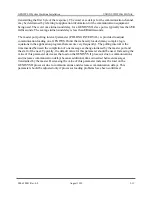
The 20 mA current loop cable should be run below ground, where it runs outside of the
equipment house or case to minimize possible lightning damage. The shield wire at the end of the
cable should be grounded using one of the 25-pin “D” connector attachment screws on the
interface panel. In addition, a rack ground wire should be run from the panel’s
EARTH GROUND
dual Fasten terminal to the equipment rack prime ground bus. Keep this wire as short as possible
and minimize the number of bends. The current loop cable should also be provided strain relief
by securing it to the rack frame with wire tie straps.
Содержание GENISYS II
Страница 4: ......
Страница 6: ...GENISYS II System Hardware Installation UNION SWITCH SIGNAL 1 2 August 1999 SM 6900B Rev 0 0 ...
Страница 12: ...UNION SWITCH SIGNAL GENISYS II System Hardware Installation 2 ii August 1999 SM 6900B Rev 0 0 ...
Страница 38: ...UNION SWITCH SIGNAL GENISYS II System Hardware Installation 2 26 August 1999 SM 6900B Rev 0 0 ...
Страница 40: ...UNION SWITCH SIGNAL GENISYS II System Hardware Installation 3 ii August 1999 SM 6900B Rev 0 0 ...
Страница 60: ...UNION SWITCH SIGNAL GENISYS II System Hardware Installation 3 20 August 1999 SM 6900B Rev 0 0 ...
Страница 62: ...UNION SWITCH SIGNAL GENISYS II System Hardware Installation 4 ii August 1999 SM 6900B Rev 0 0 ...
Страница 66: ...UNION SWITCH SIGNAL GENISYS II System Hardware Installation 4 4 August 1999 SM 6900B Rev 0 0 ...
Страница 67: ......


