GENISYS II System Hardware Installation
UNION SWITCH & SIGNAL
SM-6900B Rev. 0.0
August 1999
2-5
2.1.4 Cardfile
Grounding
DO NOT
ground the GENISYS II cardfile chassis. High ground potential could create undesirable
current paths through the system. The fiberglass mounting brackets electrically insulate the
cardfile from its mounting structure.
2.2 INSTALLING THE GENISYS II CARDFILE PLUG-INS
Installation of the GENISYS II system cardfile plug-ins is a four-step process. Each of the
following steps must be performed for each circuit board to be installed:
1.
Selecting the appropriate cardfile slot for each circuit board (Section 2.2.1).
2.
Configuring the cardfile keying plugs for each circuit board (Section 2.2.2).
3.
Configuring the circuit board jumpers and firmware just prior to installation (Section 2.2.3).
4.
Install the circuit boards (Section 2.2.4)
2.2.1 Circuit Board Installation Rules
Observe the following arrangement rules when installing GENISYS II printed circuit boards and
a local control panel (when applicable) into the cardfile:
A.
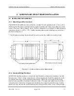
Refer to Figure 2-3. With the following exceptions, any plug-in PCB may be installed in
any cardfile slot:
Slot 19 cannot be used because there is no corresponding buss connector.
Power supply PCB N17063001, which has a two-slot-wide front panel, should be
installed in slot 18.
If the cardfile is to be equipped with a local control panel, non-vital I/O PCB
(N17002801) must be positioned behind the local control panel, so that the rear 96-
pin connector on the local control panel engages the front connector of the I/O board.
For example, if the LCP covers slots 1 through 5, the non-vital I/O board must be
installed in slot 5. Additional LCP sections may be installed as space permits. Any
combination of N17062901 and N17062902 panel sections may be installed.
US&S recommends that the CPU board should be installed in slot 16, beside the
power supply board.
B.
Any two boards can be installed adjacent to one another without concern for EMI or RF
effects between the boards. Typically, the boards are grouped according to general function.
Содержание GENISYS II
Страница 4: ......
Страница 6: ...GENISYS II System Hardware Installation UNION SWITCH SIGNAL 1 2 August 1999 SM 6900B Rev 0 0 ...
Страница 12: ...UNION SWITCH SIGNAL GENISYS II System Hardware Installation 2 ii August 1999 SM 6900B Rev 0 0 ...
Страница 38: ...UNION SWITCH SIGNAL GENISYS II System Hardware Installation 2 26 August 1999 SM 6900B Rev 0 0 ...
Страница 40: ...UNION SWITCH SIGNAL GENISYS II System Hardware Installation 3 ii August 1999 SM 6900B Rev 0 0 ...
Страница 60: ...UNION SWITCH SIGNAL GENISYS II System Hardware Installation 3 20 August 1999 SM 6900B Rev 0 0 ...
Страница 62: ...UNION SWITCH SIGNAL GENISYS II System Hardware Installation 4 ii August 1999 SM 6900B Rev 0 0 ...
Страница 66: ...UNION SWITCH SIGNAL GENISYS II System Hardware Installation 4 4 August 1999 SM 6900B Rev 0 0 ...
Страница 67: ......


