CIB UNIGAS - M039177CA
25
ADJUSTING AIR AND GAS FLOW RATES
Gas Filter (Fig. 31 - 1)
The gas filters remove the dust particles that are present in the gas, and prevent the elements at risk (e.g.: burners, counters and regu-
lators) from becoming rapidly blocked. The filter is normally installed upstream from all the control and on-off devices.
Servocontrol (Fig. 31- 5)
Two servocontrol models can be provided:
z
Berger STM30.. (see pag. 28) or
z
Siemens SQL33.. (see pag. 30).
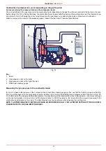
Fig. 31
Keys
1
Gas filter
2
Gas proving system
3
Gas valves
4
Adjusting cam
5
Servocontrol
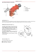
VPS504 Gas proving system (Fig. 31 - 3)
The VPS504 check the operation of the seal of the gas shut
off valves. This check is carried out as soon as the boiler
thermostat TAB gives a start signal to the burner, creating,
by means of the diaphragm pump inside it, a pressure in the
test space of 20 mbar higher than the supply pressure.
When wishing to monitor the test, install a pressure gauge
into the pressure supply point PA.
If the test cycle is satisfactory, after a few seconds the con-
sent light LC (yellow) comes on. Otherwise, the lockout light
LB (red) comes on.
To restart, it is necessary to reset the appliance by pressing
the pushbutton LB.
Fig. 32
3
4
5
1
2
LC
LB
PA
Содержание TP512A
Страница 43: ...CIB UNIGAS M039177CA 43 Wiring diagram 21 001 2 Progressive burners ...
Страница 44: ...CIB UNIGAS M039177CA 44 Wiring diagram 21 001 2 Fully modulating burners ...
Страница 46: ...CIB UNIGAS M039177CA 46 ...
Страница 47: ...CIB UNIGAS M039177CA 47 ...
Страница 48: ...CIB UNIGAS M039177CA 48 ...
Страница 49: ...CIB UNIGAS M039177CA 49 WIRING DIAGRAM Cod 09 315 1 Burners type TP525A Mod M MD x xx x 1 xx ...
Страница 50: ...CIB UNIGAS M039177CA 50 ...
Страница 51: ...CIB UNIGAS M039177CA 51 ...
Страница 52: ...CIB UNIGAS M039177CA 52 ...
Страница 55: ...CIB UNIGAS M039177CA 55 ...
Страница 56: ......

