CIB UNIGAS - M039177CA
16
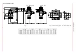
GAS TRAIN CONNECTIONS
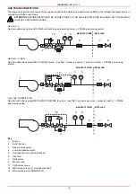
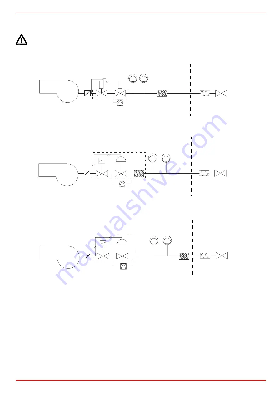
The diagrams show the components of the gas trai included in the delivery and which must be fitted by the installer.The diagrams are in
compliance with the current laws.
ATTENTION: BEFORE EXECUTING THE CONNECTIONS TO THE GAS PIPE NETWORK, BE SURE THAT THE MANUAL
SHUTOFF COCKS ARE CLOSED.
Key
1
Burner
2
Butterfly valve
3
Gas proving system
4
Low gas pressure switch
5
High gas pressure switch (optional)
6
Gas filter
7
Bellow joint
8
Manual cock
11
VGD valves group
18
MBC valves group (2”, provided with filter)
19
MBC valves group (DN65/80/100)
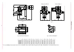
Gas train - 1
Gas train with valves group VGD 20/40 with built-in gas pressure go VPS504 gas proving system
Gas train - 2 (Rp2)
Gas train with valves group MBC 1200SE(2 gas pressure go pressure switch) + VPS504 gas proving
system
Gas train 3(DN65/80/100)
Gas train with valves group MBC 1900/3100/5000SE (2 gas pressure go pressure switch) + VPS504
gas proving system
1
2
5
4
6
7
8
10
3
MANUFACTURER
INSTALLER
1
2
3
5
4
7
8
18
MANUFACTURER
INSTALLER
1
2
3
5
4
7
8
6
19
MANUFACTURER
INSTALLER
Содержание TP512A
Страница 43: ...CIB UNIGAS M039177CA 43 Wiring diagram 21 001 2 Progressive burners ...
Страница 44: ...CIB UNIGAS M039177CA 44 Wiring diagram 21 001 2 Fully modulating burners ...
Страница 46: ...CIB UNIGAS M039177CA 46 ...
Страница 47: ...CIB UNIGAS M039177CA 47 ...
Страница 48: ...CIB UNIGAS M039177CA 48 ...
Страница 49: ...CIB UNIGAS M039177CA 49 WIRING DIAGRAM Cod 09 315 1 Burners type TP525A Mod M MD x xx x 1 xx ...
Страница 50: ...CIB UNIGAS M039177CA 50 ...
Страница 51: ...CIB UNIGAS M039177CA 51 ...
Страница 52: ...CIB UNIGAS M039177CA 52 ...
Страница 55: ...CIB UNIGAS M039177CA 55 ...
Страница 56: ......

