12
PG-I Series | Version 1.03
Operating elements and functions
LED displays
The LED lights indicate the correct operation or a fault of
the generator
Control lamp AC (green):
The LED lights up as soon as the motor runs and gene-
rates voltage.
Overload indicator (red):
The LED lights up
- as soon as one of the connected consumers
consumes more current than the generator can
produce,
- if the control unit of the inverter heats up too much
- when the AC output voltage rises above the nomi-
nal value.
The (green) mains indicator light flickers while the red
LED of the overload indicator flashes. The motor swit-
ches off.
Take the following measures when the overload indica-
tor lights up:
Step 1: Switch off all connected electrical devices and
also the motor.
Step 2: Reduce the total power of the connected loads to
be below the nominal value.
Step 3: Remove any blockages in the cooling openings
and around the control unit; improve ventilation
or cooling if necessary.
Step 4: After having eliminated the causes of the over-
load, start the motor again.
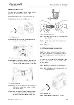
Oil indicator light (red):
As soon as the engine oil level drops below the required
minimum level, this light switches on and the engine
stops automatically. The engine can only be restarted af-
ter the oil has been topped up and the correct level has
been reached.
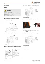
ON/OFF switch for the motor
To start the generator, the switch must be set to "I". If the
switch is set to "O", the engine is stopped and cannot be
started.
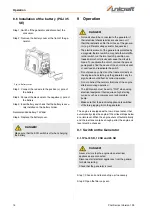
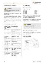
DC circuit breaker
The DC protection switches off the unit automatically if
the load exceeds the generator nominal power.
Reduce the load to the specified nominal generator out-
put until the circuit breaker releases the unit.
Fig. 11: DC circuit breaker
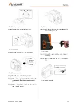
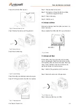
Venting button Tank cap
The fuel cap is equipped with a vent button to stop the
flow of fuel. The bleed knob must be turned once clock-
wise from the closed position to operate the generator.
This allows fuel to flow to the carburetor and the engine
to run.
When the engine is not running, tighten the bleed knob
counterclockwise until it is finger tight to stop fuel flow.
Fig. 12: Venting tank cap
NOTE!
The overload indicator can also switch on for a few
seconds if electrical loads have been connected that
require a high starting current, such as compressors,
pumps or cooling units. In this case there is no fault.
NOTE!
If the oil lamp flashes when starting and the engine
does not start, oil must be topped up before a new
starting attempt is made.
Only operate the generator on level surfaces! An
uneven stand of the generator can lead to activation
of the engine oil protection.
DC circuit breaker
Содержание PG-I 12 SR
Страница 1: ...Instruction Manual Generator PG I 8 SR PG I 12 SR PG I 20 SR PG I 35 SE PG I 12 SR PG I 35 SE...
Страница 35: ...Spare parts PG I Series Version 1 03 35 Spare parts drawing 14 Fig 68 Spare parts drawin 14 PG I 8 SR...
Страница 43: ...Spare parts PG I Series Version 1 03 43 Spare parts drawing 14 Fig 82 Spare parts drawing 14 PG I 12 SR...
Страница 51: ...Spare parts PG I Series Version 1 03 51 Spare parts drawing 14 Fig 96 Spare parts drawing 14 PG I 20 SR...
Страница 53: ...Spare parts PG I Series Version 1 03 53 Spare parts drawing 2 Fig 98 Spare parts drawing 2 PG I 35 SE...
Страница 61: ...Spare parts PG I Series Version 1 03 61 Spare parts drawing 17 Fig 113 Spare parts drawing 17 PG I 35 SE...
Страница 66: ...www unicraft de...


