


2-7
Service
TROUBLESHOOTING
BRAKES
Most electric brake malfunctions, that cannot be
corrected by either brake adjustments or synchro-
nization adjustments, can generally be traced to
electrical system failure. Voltmeters and ammeters
are essential tools for proper troubleshooting of
electric brakes. Mechanical causes are ordinar-
ily obvious, i.e. bent or broken parts, worn out
linings or magnets, seized lever arms or shoes,
scored drums, loose parts, etc. Please consult
the following troubleshooting charts in this section
of the manual to determine the causes and solu-
tions for common problems found in undercarriage
braking systems.
CAUTION! BEST BRAKING PERFORM-
ANCE IS ACHIEVED WITH A CONTROL-
LER SETTING THAT IS JUST SHORT OF WHEEL
LOCK UP OR SLIDE. OVERLY AGGRESSIVE
BRAKING WHICH RESULTS IN WHEEL LOCK
UP AND SLIDING, CAN CAUSE A DANGEROUS
LOSS OF CONTROL AND RESULT IN PERSONAL
INJURY OR DEATH.
BRAKE DRUM
INSPECTION
There are two areas of the brake drum that are
subject to wear and require periodic inspection.
These two areas are the drum surface where the
brake shoes make contact during stopping and
the armature surface where the magnet contacts
(only in electric brakes).
The drum surface should be inspected for exces-
sive wear or heavy scoring. If worn more than
.020” oversized, or the drum has worn out of
round by more than .015”, then the drum surface
should be re-machined. If scoring or other wear
is greater than .090” on the diameter, the drum
must be replaced. When turning the drum surface,
the maximum rebore diameter is as follows:
The machined inner surface of the brake drum
that contacts the brake magnet is called the
armature surface. If the armature surface is
scored or worn unevenly, it should be refaced
to a 120 micro inch fi nish by removing not more
than .030” of material. To insure proper contact
between the armature face and the magnet face,
the magnets should be replaced whenever the
armature surface is refaced and the armature
surface should be refaced whenever the magnets
are replaced.
NOTE: It is important to protect the wheel bearing
bores from metallic chips and contamination which
result from drum turning or armature refacing
operations. Make certain that the wheel bearing
cavities are clean and free of contamination before
reinstalling bearing and seals. The presence of
these contaminants will cause premature wheel
bearing failure.
BEARING INSPECTION
Wash all grease and oil from the bearing cone
using a suitable solvent. Dry the bearing with
a clean, lint-free cloth and inspect each roller
completely.
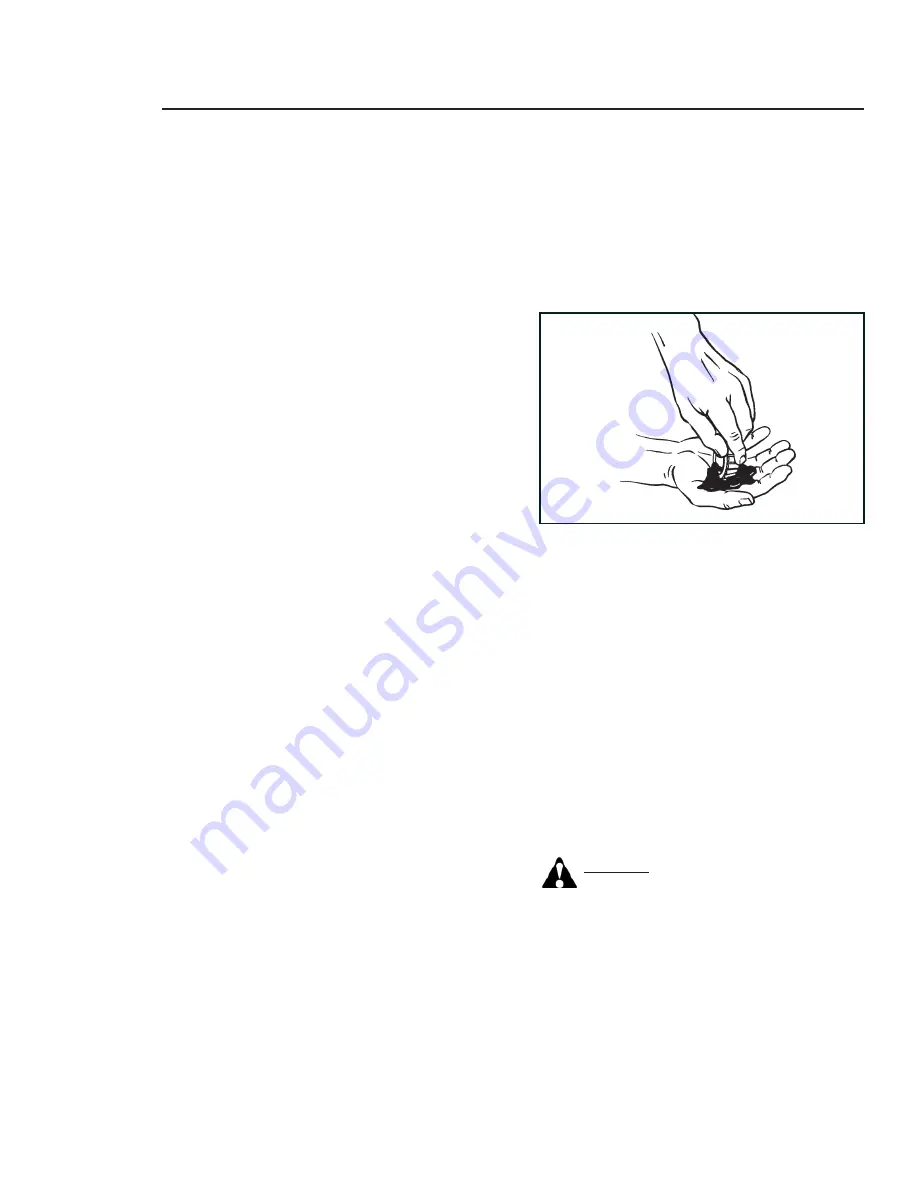
BEARING LUBRICATION
Along with bearing adjustment, proper lubrication
is essential to the proper function and reliability
of your undercarriage axle. Bearings should be
lubricated every 12 months or 12,000 miles. The
method to repack bearing cones is as follows:
1. Place a quantity of grease into the palm
of your hand.
2. Press a section of the widest end of the
bearing into the outer edge of the grease
pile closest to the thumb forcing grease
into the interior of the bearing.
3. Repeat this while rotating the bearing from
roller to roller.
4. Continue this process until you have the en-
tire bearing completely fi lled with grease.
5. Before reinstalling, apply a light coat of
grease on the bearing cup.
Содержание Unverferth 2750
Страница 12: ...12 NOTES March 2013...
Страница 28: ...Operation 1 16 NOTES...
Страница 42: ...2 14 Service MASTER DISCONNECT SWITCH ELECTRICAL SCHEMATIC...
Страница 44: ...2 16 Service TRAILER LIGHTING BRAKE ELECTRICAL SCHEMATIC...
Страница 45: ...2 17 Service SEED TANK LIGHTING ELECTRICAL SCHEMATIC...
Страница 46: ...2 18 Service NOTES...
Страница 64: ...3 18 Assembly NOTES...
Страница 65: ...4 1 Parts SECTION IV PARTS...
Страница 66: ...4 2 Parts OM04430 BOX DECALS 14 14 15...
Страница 68: ...4 4 Parts LADDER COMPONENTS OM 04435...
Страница 70: ...4 6 Parts DOOR WINDOW PIVOT COMPONENTS OM04431 Revised 082310 1 February 2013...
Страница 74: ...4 10 Parts HOPPER COMPONENTS FOR 6 TUBE CONVEYOR OM04428 February 2013...
Страница 78: ...4 14 Parts IDLER END COMPONENTS FOR 6 TUBE CONVEYOR OM04427 26 February 2013...
Страница 80: ...4 16 Parts IDLER END COMPONENTS FOR 8 TUBE CONVEYOR February 2013...
Страница 82: ...4 18 Parts DISCHARGE SPOUT COMPONENTS FOR 6 TUBE CONVEYOR OM04426 Revised 082310 1...
Страница 84: ...4 20 Parts DISCHARGE SPOUT COMPONENTS FOR 8 TUBE CONVEYOR OM04539B...
Страница 86: ...4 22 Parts HYDRAULIC COMPONENTS OM 25004A NOTE Valve is shown flipped for clarification Revised 082310 1...
Страница 94: ...4 30 Parts CABLE RETURN TARP SYSTEM COMPONENTS February 2013...
Страница 100: ...4 36 Parts AXLE WHEEL COMPONENTS Revised 082310 1...
Страница 102: ...4 38 Parts UNDERCARRIAGE ELECTRICAL COMPONENTS 24896 WIRING HARNESS...
Страница 108: ...4 44 Parts OPTIONAL GOOSE NECK HITCH COMPONENTS Front View Rear View February 2013...
Страница 111: ...4 47 Parts NOTES February 2013...
Страница 112: ...L MANUALS SEEDTENDER 27260 INDD MARCH 2013 3 JUNE 2014 4 MARCH 2015 4 www unverferth com...