


2-6
Service
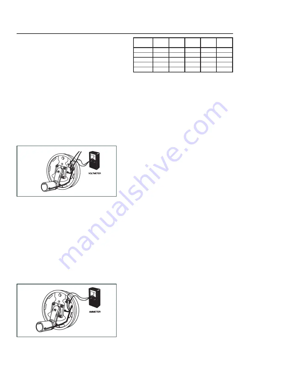
HOW TO MEASURE
VOLTAGE
System voltage is measured at the magnets by
connecting the voltmeter to the two magnet lead
wires at any brake. This may be accomplished by
using a pin probe inserted through the insulation
of the wires. The engine of the towing vehicle
should be running when checking the voltage so
that a low battery will not affect the readings.
Voltage in the system should begin at 0 volts
and, as the controller bar is slowly actuated,
should gradually increase to about 12 volts. If the
controller does not produce this voltage control,
consult your controller manual. The threshold
voltage of a controller is the voltage applied to
the brakes when the controller fi rst turns on.
Lower threshold voltage will provide for smoother
braking. If the threshold voltage is too high, the
brakes may feel grabby and harsh.
HOW TO MEASURE
AMPERAGE
System amperage is the current fl owing in the
system when all the magnets are energized. The
amperage will vary in proportion to the voltage.
The engine of the tow vehicle should be running
with the undercarriage connected when checking
the undercarriage braking system. One place
to measure system amperage is at the BLUE
wire of the controller which is the output to the
brakes. The BLUE wire must be disconnected
and the ammeter put in series into the line.
System amperage draw should be as noted in
the following table.
Make sure your ammeter has suffi cient capacity
and note polarity to prevent damaging your am-
meter. If a resistor is used in the brake system,
it must be set at zero or bypassed completely to
obtain the maximum amperage reading. Individual
amperage draw can be measured by inserting the
ammeter in the line at the magnet you want to
check. Disconnect one of the magnet lead wire
connectors and attach the ammeter between the
two wires. Make sure that the wires are properly
reconnected and sealed after testing is completed.
The most common electrical problem is low or no
voltage and amperage at the brakes. Common
causes of this condition are:
1. Poor electrical connections
2. Open circuits
3. Insuffi cient wire size
4. Broken wires
5. Blown fuses (fusing of brakes is not rec-
ommended)
6. Improperly functioning controllers or resis-
tors
Another common electrical problem is shorted or
partially shorted circuits (indicated by abnormally
high system amperage). Possible causes are:
1. Shorted magnet coils
2. Defective controllers
3. Bare wires contacting a grounded object
Finding the cause of a short circuit in the sys-
tem is done by isolating one section at a time.
If the high amperage reading drops to zero by
unplugging the undercarriage, then the short is
in the undercarriage. If the amperage reading
remains high with all the brake magnets discon-
nected, the short is in the undercarriage wiring.
All electrical troubleshooting procedures should
start at the controller. Most complaints regarding
brake harshness or malfunction are traceable to
improperly adjusted or nonfunctional controllers.
See your controller manufacturer’s data for proper
adjustment and testing procedures. For best re-
sults, all the connection points in the brake wiring
should be sealed to prevent corrosion. Loose or
corroded connectors will cause an increase in
resistance which reduces the voltage available
for the brake magnets.
Brake
Amps/
Two
Four
Six
Magnet
Size
Magnet Brakes
Brakes
Brakes
Ohms
7 x 1¼
2.5
5.0
10.0
15.0
3.9
10 x 1½
3.0
6.0
12.0
18.0
3.2
10 x 2¼
3.0
6.0
12.0
18.0
3.2
12 x 2
3.0
6.0
12.0
18.0
3.2
12¼ x 2½
3.0
6.0
12.0
18.0
3.2
Содержание Unverferth 2750
Страница 12: ...12 NOTES March 2013...
Страница 28: ...Operation 1 16 NOTES...
Страница 42: ...2 14 Service MASTER DISCONNECT SWITCH ELECTRICAL SCHEMATIC...
Страница 44: ...2 16 Service TRAILER LIGHTING BRAKE ELECTRICAL SCHEMATIC...
Страница 45: ...2 17 Service SEED TANK LIGHTING ELECTRICAL SCHEMATIC...
Страница 46: ...2 18 Service NOTES...
Страница 64: ...3 18 Assembly NOTES...
Страница 65: ...4 1 Parts SECTION IV PARTS...
Страница 66: ...4 2 Parts OM04430 BOX DECALS 14 14 15...
Страница 68: ...4 4 Parts LADDER COMPONENTS OM 04435...
Страница 70: ...4 6 Parts DOOR WINDOW PIVOT COMPONENTS OM04431 Revised 082310 1 February 2013...
Страница 74: ...4 10 Parts HOPPER COMPONENTS FOR 6 TUBE CONVEYOR OM04428 February 2013...
Страница 78: ...4 14 Parts IDLER END COMPONENTS FOR 6 TUBE CONVEYOR OM04427 26 February 2013...
Страница 80: ...4 16 Parts IDLER END COMPONENTS FOR 8 TUBE CONVEYOR February 2013...
Страница 82: ...4 18 Parts DISCHARGE SPOUT COMPONENTS FOR 6 TUBE CONVEYOR OM04426 Revised 082310 1...
Страница 84: ...4 20 Parts DISCHARGE SPOUT COMPONENTS FOR 8 TUBE CONVEYOR OM04539B...
Страница 86: ...4 22 Parts HYDRAULIC COMPONENTS OM 25004A NOTE Valve is shown flipped for clarification Revised 082310 1...
Страница 94: ...4 30 Parts CABLE RETURN TARP SYSTEM COMPONENTS February 2013...
Страница 100: ...4 36 Parts AXLE WHEEL COMPONENTS Revised 082310 1...
Страница 102: ...4 38 Parts UNDERCARRIAGE ELECTRICAL COMPONENTS 24896 WIRING HARNESS...
Страница 108: ...4 44 Parts OPTIONAL GOOSE NECK HITCH COMPONENTS Front View Rear View February 2013...
Страница 111: ...4 47 Parts NOTES February 2013...
Страница 112: ...L MANUALS SEEDTENDER 27260 INDD MARCH 2013 3 JUNE 2014 4 MARCH 2015 4 www unverferth com...