


YK11-0016-DI-002-08
22
2.6
Designing Pumping System
The following is a short note of the knowledge required in using a mechanical booster pump.
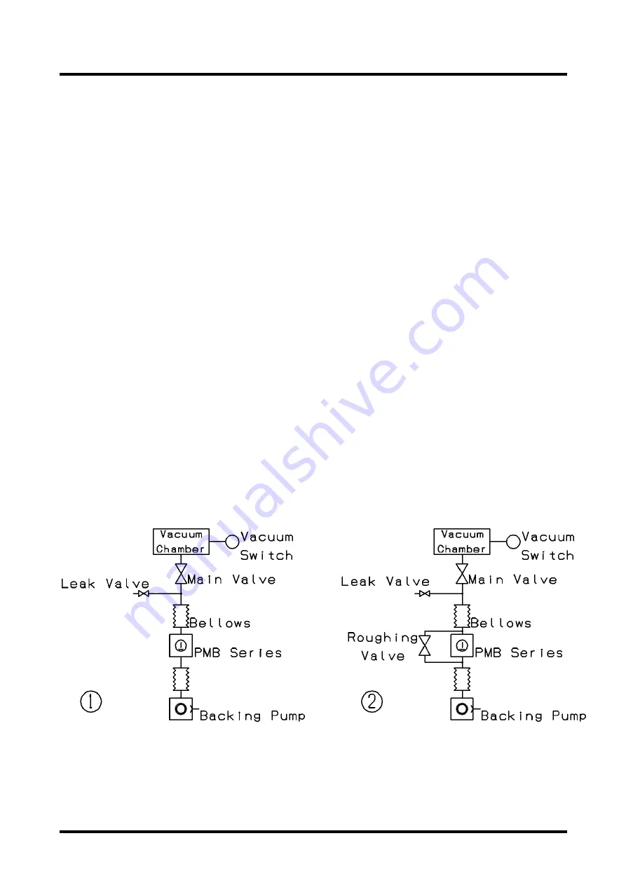
The mechanical booster pump cannot be started at the atmospheric pressure and must always be
used in combination with a backing pump (dry pump/rotary pump). Therefore, the vacuum chamber
and the piping must be rough-pumped by the methods shown in the “Fig. 19” and the mechanical
booster pump must be started after the pressure has lowered to its operating range.
The rough-pumping methods include those shown by
①
and
②
in Fig. 19.
The method
①
carries out rough-pumping through the mechanical booster pump. This method is
used when the vacuum chamber is small in size, that is, when a long time can be spent for rough-
pumping. Since the mechanical booster pump does not operate when rough-pumping is under
way, the gas to be exhausted is discharged through the clearances between the rotors in the
mechanical booster pump. This increases the pumping resistance (decreases conductance) and a
long rough-pumping time is required.
In the method
②
, a rough-pumping circuit is provided for the mechanical booster pump. This
method is used when the vacuum chamber is large in size, that is, when it is desired to shorten the
rough-pumping time.
Rough-pumping is carried out with the main valve and the roughing valve opened and, when the
specified pressure is attained, the mechanical booster pump is actuated and the roughing valve is
closed for high vacuum pumping.
Fig. 22 Evacuation by mechanical booster pump (example)
Содержание PMB100D
Страница 2: ......
Страница 3: ...Declaration of Conformity...
Страница 39: ...YK11 0016 DI 002 08 12 2 4 Dimensional drawing Fig 11 Dimensional drawing PMB100D...
Страница 40: ...YK11 0016 DI 002 08 13 Fig 12 Dimensional drawing PMB300D...
Страница 41: ...YK11 0016 DI 002 08 14 Fig 13 Dimensional drawing PMB600D...
Страница 42: ...YK11 0016 DI 002 08 15 Fig 14 Dimensional drawing PMB1200D...
Страница 43: ...YK11 0016 DI 002 08 16 Fig 15 Dimensional drawing PMB2400D...
Страница 62: ...YK11 0016 DI 002 08 35...
Страница 65: ...YK11 0016 DI 002 08 38...
Страница 72: ...YK11 0016 DI 002 08 45...
Страница 83: ...YK11 0016 DI 002 08 56 5 7 Optional attachment figure Fig 27 PMB100D Optional attachment figure...
Страница 84: ...YK11 0016 DI 002 08 57 Fig 28 PMB300D Optional attachment figure...
Страница 85: ...YK11 0016 DI 002 08 58 Fig 29 PMB600D Optional attachment figure...
Страница 86: ...YK11 0016 DI 002 08 59 Fig 30 PMB1200D Optional attachment figure...
Страница 88: ...YK11 0016 DI 002 08 61 Fig 32 PMB2400D Optional attachment figure If you have installed the inlet ISO K flange...
Страница 89: ...YK11 0016 DI 002 08 62 Fig 33 Dimensional drawing PMB2400D Horizontal exhaust model...
Страница 99: ...YK11 0016 DI 002 08 72...
Страница 105: ...YK11 0016 DI 002 08 78...
Страница 119: ......


