


YK11-0016-DI-002-08
9
in the connection.
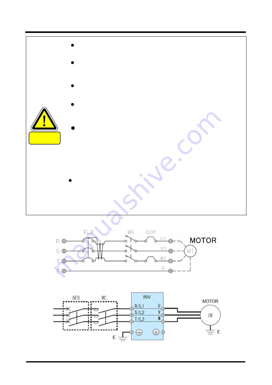
Fig. 6
①
Recommended connection diagram
Fig. 7
②
Recommended connection diagram(INV)
CAUTION
cTUVus is, has been certified in the use of multi-voltage
counterparts motor.
When you use the pump in Quebec, Canada, French labels and
instruction manual are necessary.
Please contact beforehand.
Use of inverter enables operation with intake pressure starting from
atmospheric pressure.
(
Please refer to Section 5.4 for options.)
Inverter is CE approved marking · NRTL, with respect to installation
conditions have been noted. Refer to the instruction manual of the
inverter, please be prepared by the customer the necessary parts.
Structure of the Mechanical seal would allow a slight oil leak even
the sealing was correct.
In case you look oil to the oil level gauge at the cover of motor side,
please stop a pump, hat there is an oil leakage from
the Mechanical seal section.
You should drain out oil of the reservoir, and it relubricates the
cover on the motor side.
Oil recovery methods, see Section 3.2.2.
When there is absorption of the dust, please appoint the surface
coating to provide surface rigidity.
If you use no-coating-pump, the rotor shaft and casing surface are
damaged when there is absorption of the dust,
and the pump might lead to decrease on performance or break down.
Содержание PMB100D
Страница 2: ......
Страница 3: ...Declaration of Conformity...
Страница 39: ...YK11 0016 DI 002 08 12 2 4 Dimensional drawing Fig 11 Dimensional drawing PMB100D...
Страница 40: ...YK11 0016 DI 002 08 13 Fig 12 Dimensional drawing PMB300D...
Страница 41: ...YK11 0016 DI 002 08 14 Fig 13 Dimensional drawing PMB600D...
Страница 42: ...YK11 0016 DI 002 08 15 Fig 14 Dimensional drawing PMB1200D...
Страница 43: ...YK11 0016 DI 002 08 16 Fig 15 Dimensional drawing PMB2400D...
Страница 62: ...YK11 0016 DI 002 08 35...
Страница 65: ...YK11 0016 DI 002 08 38...
Страница 72: ...YK11 0016 DI 002 08 45...
Страница 83: ...YK11 0016 DI 002 08 56 5 7 Optional attachment figure Fig 27 PMB100D Optional attachment figure...
Страница 84: ...YK11 0016 DI 002 08 57 Fig 28 PMB300D Optional attachment figure...
Страница 85: ...YK11 0016 DI 002 08 58 Fig 29 PMB600D Optional attachment figure...
Страница 86: ...YK11 0016 DI 002 08 59 Fig 30 PMB1200D Optional attachment figure...
Страница 88: ...YK11 0016 DI 002 08 61 Fig 32 PMB2400D Optional attachment figure If you have installed the inlet ISO K flange...
Страница 89: ...YK11 0016 DI 002 08 62 Fig 33 Dimensional drawing PMB2400D Horizontal exhaust model...
Страница 99: ...YK11 0016 DI 002 08 72...
Страница 105: ...YK11 0016 DI 002 08 78...
Страница 119: ......


