


TROUBLESHOOTING
A GENERAL:
The problems and possible solutions listed in the troubleshooting chart below are typical problems that are frequently encountered.
ONLY
qualified repairmen are to use the troubleshooting chart to repair this fryer. In the event a main burner malfunction occurs, perform the
following checks
PRIOR
to contacting a repairman:
1. Ensure Gas Valves are in their proper position.
2. Check that the fryer electrical plug is connected to an electrical receptacle.
3. Ensure the applicable Circuit Breaker is in the
ON
position and that the fryer ON/OFF switch is in the
ON
position.
4. Ensure the applicable fryer control has been placed in the
FULL ON
mode.
5. Ensure the gas supply line quick-disconnect coupling is
SEATED
on the gas manifold fitting.
6. Determine that the blower is operating.
B TROUBLESHOOTING CHART:
Should a problem occur that cannot be corrected after performing the above CHECKS, contact an
authorized repairman and/or Ultrafryer Systems Systems Customer Service 1-800-525-8130 and provide the information acquired while
performing these checks.
CAUTION: ENSURE REPAIRMEN ARE ADVISED THAT FRYER RESTRAINTS MUST BE DISCONNECTED/CONNECTED.
IF A FRYER IS TO BE MOVED DURING MAINTENANCE OR REPAIR, AND THAT ELECTRICAL POWER AND GAS
MUST BE TURNED OFF PRIOR TO PERFORMING ANY MAINTENANCE OR REPAIR.
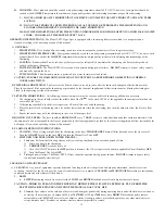
TROUBLESHOOTING CHART
ISSUE
PROBLEMS
POSSIBLE SOLUTIONS
1
Main burner will not ignite. Blower is operating;
but gas is not present at the burner.
A. Check the Blower Motor air pressure Switch by temporarily discon-
necting the two (2)
ORANGE
blower motor wires and connecting
them together. If the
IGNITOR
sparks when these wires are con-
nected, the air pressure switch is defective and it will have to be
replaced.
B. Check the following components and replace if found to be
defective: Gas Control Valve
Hi-Limit Switch
Transformer
2
Electrical power is present at the fryer, but the
Blower is not operating.
A. Blower Motor may have over-heated and shut off on thermal over-
load. If this situation did occur, it will correct itself when the mo-
tor cools (10-20 minutes). If this overheating problem persists, re-
place the blower motor
.
3
Excessive time is required to raise the shortening to
cooking temperature. Temperature recovery is slow
and main burner flames are small and appear to be
lethargic.
A. Ensure that the MANUAL GAS VALVE is completely open.
B. Check for an obstruction in the gas line.
C. Check for an obstruction in the flue pipe.
D. Check that the ORFICE PLUG has the correct drill size opening as
indicated on the operational requirements on the chart shown on
page 3.
E. Check for damaged BLOWER MOTOR fins.
F. Use a standard water-type U-gauge Manometoer to check the pres-
sure at the gas control valve pressure tap. Proper gas pressure is
indicated on the operational requirementschart shown on page 3.
NOTE:
If necessary remove the Pressure Regulator Adjustment Cover and
adjust this control to the proper pressure.
(Turn adjusting screw
CLOCK-
WISE
to increase
gas pressure to the burner and
COUNTER CLOCKWISE
to decrease
gas pressure. Replace adjustment cover.)
4
Shortening temperature is too high and breaks down
quickly.
A. Check the gas pressure as described above.
B. Check calibration of the Fenwal Temperature or Electronic
Thermostat with an
ACCURATE
digital thermometer.
5
The filter pump motor fails to operate when the Vat
Shortening Return / Topside Shortening Lever is
placed in the
OPEN
position.
A. Insure the filter pump micro-switch is good, then check the manual
reset button on the filter pump motor.
B. If the filter pump motor fails to operate after the reset button has
been depressed, repair or replace the motor.
6
Decreased shortening flow rate while filtering.
A. Check for excessive sediment on the filter screen, standpipe suction
fitting or in filter tub.
7
Pump/Motor operates but does not pump shoretening. A. Check for congealed shortening in the shortening system.
B. Check for loose Standpipe / Suction Line Coupler connection.
8
Pump / Motor hums but will not pump shortening
A. Check for congealed shortening in the pump or in shortening
plumbing.
15


