background image

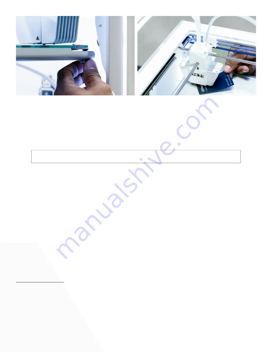
After calibrating the build plate with the first nozzle, the second nozzle needs to be aligned as well, to ensure the 
heights of both nozzles are set correctly. For this it is only necessary to set the correct height by using the calibra-
tion card.

Place the calibration card between the second nozzle and build plate.
Rotate the button at the front of the Ultimaker 3 until it touches the calibration card and fine-tune it until you feel 
slight friction/resistance when moving the card.
Press the button to confirm and complete the calibration process.


CAUTION: Do not push on the build plate while fine-tuning with the calibration card. This will lead 


     to inaccuracies.

Z offset calibration
The last part of the manual leveling procedure is the Z offset calibration. This ensures that the correct vertical dis-
tance between the two nozzles is stored. This procedure can also be done separately.

Go to System > Maintenance > Calibration > Calibrate XY offset.
Place the calibration card between the second nozzle and build plate.
Rotate the button at the front of the Ultimaker 3 until it touches the calibration card and fine-tune it until you feel 
slight friction/resistance when moving the card.

XY offset calibration
Besides the vertical offset, the horizontal distance between the nozzles, in the X and Y direction, also needs to be 
stored. The print cores that are supplied with the Ultimaker 3 are already calibrated. This is only necessary for new 
combinations.

A correct XY calibration will ensure that the two colors or materials align well.

To do the calibration you will need the XY calibration sheet, which you can find in the accessory box. You also 
need to make sure two print cores and materials are loaded.

To start the calibration:
 

1. 

Go to System > Maintenance > Calibration > Calibrate XY offset.


2. 

The Ultimaker 3 will now print a grid structure on the build plate. Wait until it is finished.


3. 

Once the Ultimaker 3 has cooled down, remove the glass plate from the printer and place it on the   


XY calibration sheet. Ensure the printed grid it is exactly placed on the two rectangles on the sheet.


4. 

Find the aligned lines on the printed X grid and look which number belongs to these lines. Enter    


this number as the X offset value on your Ultimaker 3.


5. 

Find the aligned lines on the printed Y grid and look which number belongs to these lines. Enter    


this number as the Y offset value on your Ultimaker 3.

14

Содержание 3 Extended

Страница 1: ...Training Creation of the UltimakerTraining Program V1 1 Hand out Ultimaker 3 to end user...

Страница 2: ...Table of contents 3D print basics Setting up your Ultimaker 3 Features explained Calibrations Materials Cura Maintenance ESD safety Support 1 4 9 13 16 19 27 32 33...

Страница 3: ...ip the filament and transport it up through the bowden tubes The bowden tubes guide the filament to the print head and into the print cores The filament only gets heated up in the heater block right a...

Страница 4: ...The Z stage or build plate slides over the two vertical Z axles but the movement is controlled by the long lead screw This is connected to the Z motor UltiController You can control the printer throu...

Страница 5: ...to place the print head the position of the build plate how much filament should be extruded etc A 3D design is turned into a gcode by the software program Cura Later on you will learn how this works...

Страница 6: ...ing the buckle 3 Remove the top part of the styrofoam packaging with the two spools of filament and factory test print in it 4 Take out the accessory box 5 Remove the styrofoam part that is placed at...

Страница 7: ...The flat side of the connector faces away from the bottom panel 4 Guide the NFC cable through the slot in the back panel 5 Insert the cable cover into the back panel to keep the cable in place 6 Gent...

Страница 8: ...After this you can go through all the menus while doing what the printer is telling you Print core installation The first step of the welcome wizard is installing the second print core As you can see...

Страница 9: ...print core 2 and to load the material into the print head 5 Confirm when the new material extrudes from the print head 6 Wait a moment for print core 2 to cool down Loading material 1 1 Take the mate...

Страница 10: ...the wireless network of the printer The name of the net work is shown on the display of the Ultimaker 3 3 A pop up will appear on the display of your computer Follow the steps to connect the Ultimaker...

Страница 11: ...Nozzle lifting system 2 Excellent cooling 3 Silicone cover 4 Capacative sensor 1 2 3 4 Print head overview Print head Build volumes The Ultimaker 3 has many new innovative features Learn how they wor...

Страница 12: ...bay which places the lifting switch to the front or back Excellent cooling The print head of the Ultimaker 3 has three fans The two radial fans at the side cool the model during printing for optimal...

Страница 13: ...sed for printing support material The difference is the internal geometry The AA print core has a small horizontal part in the the tip This ensures higher precision and reduces oozing The BB core is d...

Страница 14: ...om the user USB button display to the Olimex Feeder The two geared feeders have been optimized for reliability The gears ensure an excellent grip on the filament during feeding and it is very easy to...

Страница 15: ...equency for active leveling CAUTION Don t touch the Ultimaker 3 during the active leveling procedure This could affect the measurements Manual leveling The Ultimaker 3 is shipped pre calibrated so man...

Страница 16: ...tion card and fine tune it until you feel slight friction resistance when moving the card XY offset calibration Besides the vertical offset the horizontal distance between the nozzles in the X andY di...

Страница 17: ...libration can also be done manually 1 Go to System Maintenance Calibration Calibrate lift switch 2 Move the lift switch on the side of the print head to point towards you 3 Move the print head so that...

Страница 18: ...eamless connection between the printer and Cura software Material combinations If you want to print with two materials on the Ultimaker 3 the following material combinations are officially supported P...

Страница 19: ...et these manually Material Nozzle temperature C Build plate temperature C PLA 195 205 60 ABS 225 240 80 CPE 235 250 70 Nylon 245 255 60 PVA 215 225 60 Adhesion methods For all the materials that are c...

Страница 20: ...ctly this may cause the material to lose quality over time Some materials may become brittle when handled or stored incorrectly and others may absorb too much moisture To keep your filaments in optima...

Страница 21: ...now 1 Go to the WiFi manager in your operating system and search for the available new network that the Ultimaker 3 created 2 Connect to the network and wait for it to connect 3 A pop up window appea...

Страница 22: ...onizing the nozzle and material information with the Ultimaker 3 Since this is a first run the nozzle and materials in the Ultimaker 3 differ from the Cura setup Click Yes to synchronize the Ultimaker...

Страница 23: ...ettings at which your model in the 3D viewer is going to be sliced Printer monitor The connection status between Cura and the Ultimaker 3 is visualized in the top right corner of the sidebar The print...

Страница 24: ...ura can synchronize with the Ultimaker 3 automatically just like it did on first setup When the Ultimaker 3 is network connected the option automatic is available for the Print Cores and materials Go...

Страница 25: ...print 5 Support extruder Choose which print core prints the support structure 6 Build plate adhesion Choose if extra adhesion is desired it is turned on by default Printing workflows PLA PVA soluble...

Страница 26: ...core 2 BB PVA 4 You have to select a profile to print this model with Depending on the purpose of the model choose a profile that fits it Examples Prototype Fast print End part High quality 5 Select...

Страница 27: ...color 2 3 All loaded objects are printed with Print core 1 by default The material color set per Print Core reflects the color of the corresponding model Left click the model you want to print with ex...

Страница 28: ...el choose a profile that fits it Examples Visual aid Fast print End part High quality 7 Select Helper Parts on the Sidebar Since you use PLA in both extruders you can print the supports with either of...

Страница 29: ...ick in the Ultimaker 3 4 Go to System Maintenance Update firmware 5 The Ultimaker 3 will detect it if there is a firmware file on the USB stick Select the file to start the firmware update Lubricating...

Страница 30: ...dry it with a cloth If necessary you can also use some soap Place the glass plate back onto the build plate and close the build plate clamps at the front side to secure it CAUTION Leaving the build pl...

Страница 31: ...er Small pieces of material can gather inside the printer including the initial extrusions Remove these from the inside of the printer with a cloth or vacuum cleaner CAUTION Leaving larger objects on...

Страница 32: ...ing 1 Remove or retract the filament 2 Place the print head in the front right corner to prevent bending the axles 3 Remove the white clip from the bowden tube and press down on the tube coupling coll...

Страница 33: ...ture 2 Hold the filament with pliers and gently apply pressure to extrude some material 3 Lower the nozzle temperature to approximately 20 C above the filament s build plate temperature 4 Wait until t...

Страница 34: ...way when handling them When working with the Ultimaker 3 in a normal way you don t have to worry about ESD Any charge that you may have built up is dispersed through the metal parts of the frame Howe...

Страница 35: ...ertified of the needed global labels More information and downloadable documents are availale at the Safety Compliance webpage from Ultimaker Labels the Ultimaker 3 is certified for VPAT Voluntary pro...

Отзывы: