


HT 10/11/20
30
producto dentro de los contenedores está frio, es señal de que
todo funciona bien y que el calor producido no es alarmante.
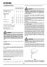
5
Regulación de la temperatura: para este tipo de operación,
dirigerse exclusivamente al técnico.La temperatura ideal de las
bebidas ha sido establecida y regulada en la fábrica.
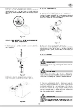
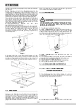
6
Para reducir la espuma que ciertos productos (café, té,
horchada, etc.) producen al ser removidos por la bomba, se
puede aplicar al grupo un dispositivo reductor de flujo y el
propio tubo curvo (ver figura 2).
figura 2
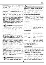
7
Serie HT10 con tapas iluminadas: para cambiar la
orientación de la tapa, quitar los tornillos y girar de 180° la
parte superior de la tapa, que contiene la fotografia, sin
modificar la posición de la tapa secundaria. Fijar con los
tornillos (ver figura 3).
figura 3
5. 3 LIMPIEZA
La limpieza y el lavado son fundamentales para garantizar la
perfecta conservación del gusto de la bebida y la máxima
eficiencia de vuestro distribuidor. Los procedimientos descritos
a continuación deben ser considerados de carácter general y
pueden variar por efecto de la reglamentación de higiene
vigente.
Antes del desarmado para el lavado del distribuidor debe
quitarse todo el producto.
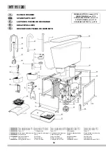
5. 3. 1 DESMONTAJE
1
Quitar la tapa del contenedor.
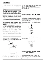
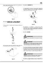
2
Series HT11 - HT20PS:
quitar el grupo bomba girándolo en
sentido horario (1) y levantándolo(2). Desmontar el tubo de
mandata y el tubo a “L”. Para desmontar la turbina y el eje del
grupo bomba, desenganchar la clavija de fijación (ver figura 4).
figura 4
3
Serie HT10 - HT20M:
quitar el agitador retirándolo hacia
arriba.
4
Quitar el contenedor vacío levantándolo por la parte del
grifo y desprendiéndolo del evaporador de acero.
5
Quitar la junta del contenedor.
6
Ver párrafo 5.3.2. SMONTAGGIO RUBINETTO.
7
Sacar el cajón recoge-gotas y vaciarlo.
5. 3. 2 DESMONTAJE GRIFO
5. 3. 2. 1 SERIES HT11 - HT20. GRIFO CON
TUBO DE GOMA
1
Empujar la palanca mando grifo (1) y sacar (2) el tubo
goma de salida desde su situación vertical en el fondo del
contenedor (ver figura 5).
figura 5
2
Desmontar el contenedor y ponerlo boca abajo.
Desenganchar (1) la palanca de desmontaje del grifo y al
mismo tiempo girar (2) hacia la izquierda (sentido antihorario)
ATTENCION
Antes de proceder con el desmontaje de cualquier com-
ponente, desenchufar de la toma de corriente eléctrica el
enchufe del aparato o bien apagar el interruptor externo
de pared.
Содержание HT10/1
Страница 39: ...39 NOTE NOTES NOTES ANMERKUNGEN NOTAS...