


HT 10/11/20
14
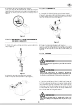
5. 3. 5 ASSEMBLY
1
Slide drip tray with its cover into place.
2
See 5.3.6 FAUCET ASSEMBLY paragraph
3
Fit bowl gasket to the bowl leaving the thickest part of it out-
side the bowl (see figure 9).
figure 9
4
Place bowl on the unit, with gasket around the cooling
dome, then push it down all the way.
Wet cooling dome and gasket for ease of insertion.
5
HT11 - HT20 PS lines
: raessemble pump assembly; place
it into bowl location and turn it counterclockwise until it stops
into position.
6
HT10 - HT20M lines
: replace stirrer onto its shaft and drop
it into place freely.
5. 3. 6 FAUCET ASSEMBLY
5. 3. 6. 1 HT11 - HT20 LINES WITH PINCH
TUBE FAUCET
1
Fit the faucet cover and the faucet body by reversing disas-
sembly operations (see figure 5).
2
Push (1) the dispensing handle and insert (2) the pinch tube
into its vertical seat in the bowl bottom (see figure 10).
figure 10
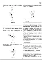
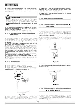
3
Lightly pull (3) the pinch tube end downwards till it is well
arranged. (see figure 11).
figure 11
5. 3. 6. 2 HT11 - HT20 LINES WITH GRAVITY
FAUCET
1
Fit the faucet body by reversing disassembly operations
(see figure 7).
2
Install the faucet handle (1-2) and the piston with its gasket
(3) (see figure 12).
figure 12
5. 3. 6. 3 HT10 LINE
1
Fit the faucet cover and the faucet body by reversing disas-
sembly operations (vedere figure 5).
2
Insert the pinch tube into its horizontal seat in the bowl
bottom (see figure 13).
figure 13
3
Insert the pinch tube end into the faucet body vertical seat
(see figure 14).
figure 14
4
Push (1) the dispensing handle and pull the pinch tube end
Содержание HT10/1
Страница 39: ...39 NOTE NOTES NOTES ANMERKUNGEN NOTAS...


