

SARA-G450 - System integration manual
UBX-18046432 - R08
Design-in
Page 98 of 143
C1-Public
2.6.2
Secondary auxiliary serial interface (AUX UART)
☞
Secondary auxiliary UART interface is not supported by the “00” product version. This interface
should be left unconnected and should not be driven by external devices.
2.6.2.1
Guidelines for AUX UART circuit design
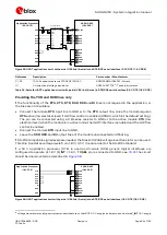
If RS-232 compatible signal levels are needed, the Maxim 13234E voltage level translator can be used.
This chip translates voltage levels from 1.8 V / 3.0 V (module side) to the RS-232 standard.
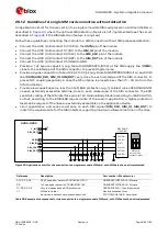
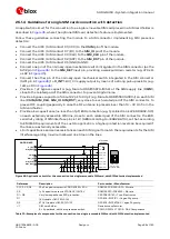
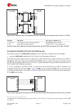
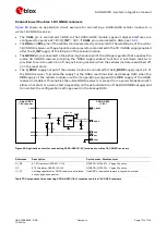
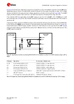
If a 1.8 V application processor (DTE) is used and module (DCE) generic digital interfaces are
configured to operate at 1.8 V (V_INT = 1.8 V, if VSEL pin is connected to GND; see
), the circuit
should be implemented as described in
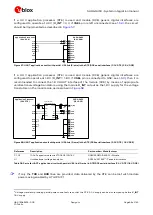
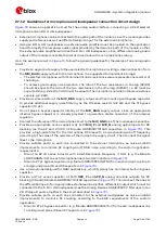
TxD
Application Processor
(1.8V DTE)
RxD
GND
SARA-G450
(1.8V DCE)
17
TXD_AUX
19
RXD_AUX
GND
21
VSEL
Figure 59: AUX UART application circuit (1.8 V DTE / 1.8 V DCE)
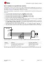
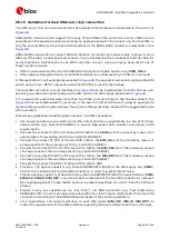
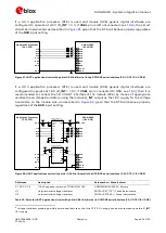
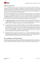
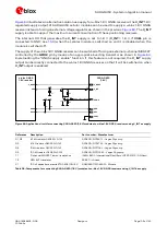
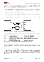
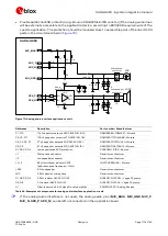
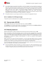
If a 3.0 V application processor (DTE) is used and module (DCE) generic digital interfaces are
configured to operate at 3.0 V (V_INT = 3 V, if VSEL pin is left unconnected; see
), the circuit
should be implemented as described in
TxD
Application Processor
(3.0V DTE)
RxD
GND
SARA-G450
(3.0V DCE)
17
TXD_AUX
19
RXD_AUX
GND
21
VSEL
Figure 60: AUX UART application circuit (3.0 V DTE / 3.0 V DCE)
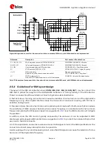
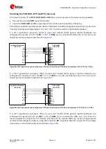
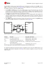
If a 3.0 V application processor (DTE) is used and module (DCE) generic digital interfaces are
configured to operate at 1.8 V (V_INT = 1.8 V, if VSEL pin is connected to GND; see
), then it is
recommended to connect the 1.8 V AUX UART interface of the module (DCE) by means of appropriate
unidirectional voltage translators using the module V_INT output as the 1.8 V supply for the voltage
translators on the module side, as described in