SARA-G450 - System integration manual
UBX-18046432 - R08
System description
Page 8 of 143
C1-Public
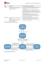
The RF section is composed of the following main elements:
2G RF transceiver performing modulation, up-conversion of the baseband I/Q signals,
down-conversion and demodulation of the RF received signals
2G Power Amplifier, which amplifies the signals modulated by the RF transceiver
RF switch, which connects the antenna input/output pin (ANT) of the module to the suitable
RX/TX path
26 MHz crystal, connected to the digital controlled crystal oscillator to perform the clock reference
in active-mode and connected-mode
The Baseband and Power Management section is composed of the following main elements:
Baseband processor
Memory system
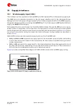
Voltage regulators to derive all the system supply voltages from the module supply VCC
Circuit for the RTC clock reference in low power idle-mode
☞
SARA-G450-00C modules, i.e. the “00” product version of the SARA-G450 modules, do not
support the following interfaces, which should be left unconnected and should not be driven by
external devices:
o
Secondary auxiliary UART interface
o
DDC (I2C) interface
o
Analog audio interface


