

SARA-G450 - System integration manual
UBX-18046432 - R08
System description
Page 26 of 143
C1-Public
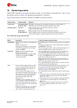
1.6.3
Module reset
SARA-G450 modules can be properly reset (rebooted) by:
AT+CFUN command (see the u-blox AT commands manual
for more details).
This command causes an “internal” or “software” reset of the module, which is an asynchronous reset
of the module baseband processor. The current parameter settings are saved in the module’s
non-volatile memory and a clean network detach is performed: this is the correct way to reset the
modules.
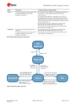
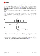
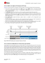
An abrupt hardware reset occurs on SARA-G450 modules when a low level is applied on the PWR_OFF
input pin and then a low level is applied on the PWR_ON input pin for specific time periods; in this way
the reset is performed with an abrupt shutdown and then switching on again the module. In this case,
the current parameter settings are not saved in the module’s non-volatile memory and a clean
network detach is not performed.
☞
It is highly recommended to avoid an abrupt hardware shutdown of the module by forcing a low
level on PWR_OFF input pin during module normal operation: the PWR_OFF line should be set low
only if reset or shutdown via AT commands fails or if the module does not reply to a specific AT
command after a time period longer than the one defined in the u-blox AT commands manual
The PWR_OFF input pin is internally connected through a series Schottky diode to 1.5 V internal
supply, keeping the line to the high logic level when the PWR_OFF pin is not forced low from the
external. See the SARA-G450 data sheet
for the detailed electrical characteristics of the PWR_OFF
input.
☞
Before the switch-on of the generic digital interface supply source (V_INT) of the module, no
voltage driven by an external application should be applied to any generic digital interface of the
modules.
☞
The internal reset state of all digital pins is summarized in the pin description table included in the
SARA-G450 data sheet
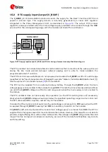
1.6.4
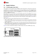
Digital I/O interfaces voltage selection (VSEL)
The digital I/O interfaces of SARA-G450 modules (the UART interfaces, I2C interface and GPIO pins)
can operate at 1.8 V or 3 V voltage rail. The operating voltage can be selected using the VSEL input
pin:
If the VSEL input pin is connected to GND, the digital I/O interfaces operate at 1.8 V
If the VSEL input pin is left unconnected, the digital I/O interfaces operate at 3 V
The operating voltage cannot be changed dynamically: the VSEL input pin configuration has to be set
before the boot of SARA-G450 modules and then it cannot be changed after switched on.