SKU 97706
For technical questions, please call 1-800-444-3353.
PAGE 20
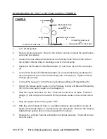
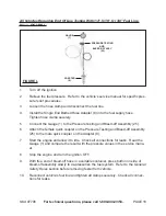
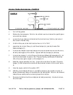
Bosch Continuous Injection System (CIS) Testing - FIGURE N:
gaUgE
(1)
PRESSURE TESTINg
aND
BLEED-OFF aSSY.
(25)
aDaPTERS
(10, 11, 12, 13, 15, 16, 18, 19, 20, 21, 22, 23, OR 24)
aND
“O-RINgS”
CIS TESTINg aSSEMBLY
WITH
BaLL VaLVE
(31)
FIgURE N
1.
Turn off the ignition.
Clean the top of the fuel distributor to keep dirt from entering the fuel system.
2.
Relieve the fuel pressure. Refer to the vehicle’s service manual for specific pres
-
3.
sure relief procedures.
The CIS system has a primary circuit with pressure regulated at the fuel distribu-
4.
tor. This is known as
supply pressure, primary pressure, or line pressure
. The
side of the tester
without
the ball valve is connected to this circuit. The other
circuit is known as the
control circuit
. This contains the control pressure regula-
tor, known as the
warm-up compensator
. The side of the test
with
the ball valve
is connected to this circuit.
Connect the Gauge (1) to the Pressure Testing and Bleed-off Assembly (25).
5.
Install Adapter(s) (10, 11, 12, 13, 15, 16, 18, 19, 20, 21, 22, 23, or 24) and “O-
6.
Ring” to the engine as required. Hand tighten only. Then connect Hoses to
Adapters.
Attach the female quick coupler on the Pressure Testing and Bleed-off Assembly
7.
(1) to the male quick coupler on the CIS Testing Assembly with Ball Valve (31).
With free end of bleed-off hose in a suitable container, press button on side of
bleed-off assembly slowly to release any air in the test Hose.
Refer to the
8.
General Safety Rules
section before removing tester from vehicle.
Remove tester and Adapters from vehicle. Reconnect vehicle’s fuel injection
lines to original condition. Start the vehicle and check for leaks.
Start the engine and check for leaks. Read the fuel pressure. Compare the
9.
value on the Gauge (1) to the value in the service manual.


