


SKU 97706
For technical questions, please call 1-800-444-3353.
PAGE 17
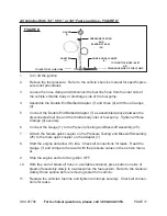
All Vehicles With 1/4”, 5/16”, or 3/8” Fuel Line Hose - FIGURE K:
gaUgE
(1)
PRESSURE TESTINg
aND
BLEED-OFF aSSY.
(25)
aDaPTER
(7)
HOSE & HOSE CLaMPS
(4)
TO INLET FUEL LINE HOSE
TO THROTTLE BODY INLET
OR
DISCHaRgE SIDE OF FUEL PUMP
FIgURE K
1.
Turn off the ignition.
Relieve the fuel pressure. Refer to the vehicle’s service manual for specific pres
-
2.
sure relief procedures.
Loosen the hose clamp and disconnect the fuel line hose from the inlet side of
3.
the vehicle’s throttle body or discharge side of the fuel pump.
Assemble the Double End Barbed Adapter (7) and Hose (4) with Hose Clamps
4.
(4).
Connect the Double End Barbed Adapter (7) as assembled above between the
5.
disconnected fuel line and the throttle body inlet or fuel pump. Tighten all Hose
Clamps (4) securely.
Connect the Gauge (1) to the Pressure Testing and Bleed-off Assembly (25).
6.
Attach the female quick coupler on the Pressure Testing and Bleed-off Assembly
7.
(25) to the male quick coupler on the Adapter (7).
Start the engine and allow it to idle. Check all connections for leaks. Read the
8.
Gauge (1) and compare the result with the pressure values in the service manu-
al.
Stop the engine and turn the ignition OFF.
9.
With free end of bleed-off hose in a suitable container, press button on side of
10.
bleed-off assembly slowly to de-pressurize the fuel system. Refer to the
General
Safety Rules
section before removing tester from vehicle.
Replace the vehicle’s fuel line and tighten all clamps securely. Check all connec-
11.
tions for leaks.