36
IX. OPERATING (continued)
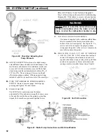
Press and release the
“
I
”
key on the Boiler Control
to change from one parameter to the next. Each
setting will alternately flash between the relevant
display code and its corresponding value.
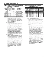
Operating Mode Options
t
Status Numbers:
Standby
Running
Self Test)
bt
Boiler Temperature
P
Operating Setpoint (Outdoor Reset)
HL
High Limit Setting
HdF
High Limit Differential
hr
Heat Request Status
dh
DHW Request Status
Err
Boiler Error
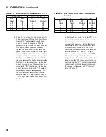
For example, when the “
I
” key is pressed on the
Boiler Control until “
bt
” is displayed, it will then
flash a three digit number (such as “
0
”) followed
by either “
F
” (or “
C
”). This indicates that the boiler
water temperature is
180°F. Other operating
parameters display the information in a similar
fashion.
Please note that in operating mode to hold the
display on the value the user can press and hold
either the Up
ñ
or Down
ò
keys and the value will
be continuously shown. This may be helpful in
watching a value “live”.
4.
Changing the Adjustable Parameters
To adjust parameters such as the High Limit
Setpoint and High Limit Differential:
a. Using the Boiler Control display, access the
adjustment mode by pressing and holding the Up
ñ
, Down
ò
, and “
I
” keys simultaneously for
three (3) seconds. This procedure is intended to
discourage unauthorized changes or accidental
changes to limit settings.
b. Press the “
I
” key to display available Adjust-
ment Mode options. Select an option.
c. Press the Up
ñ
and Down
ò
keys to adjust the
displayed setpoint to the desired value.
d. To return to the normal operating mode from the
Adjustment Mode, when the “
bc
” option is
displayed, press either the Up
ñ
or Down
ò
key.
If no keys are pressed, after five (5) minutes the
Boiler Control will automatically return to the
Operating Mode.
5.
More Information about Adjustable Parameters
a. High Limit (
HL_
)
The Boiler Control is factory programmed with a
High Limit Setpoint of 180
°
F. The boiler turns
“off” when the boiler water temperature (
bt
) is
above this value. The High Limit setpoint is
adjustable between 140
°
and 240
°
F. The
Operating Setpoint (
P
) will equal the High
Limit Setpoint.
b. High Limit Differential (
HdF
)
The Cold Start Boiler Control is factory pro-
grammed with a Differential of 15
°
F. The
Differential is the number of degrees the boiler
temperature must decrease below the Operating
Setpoint before the boiler can restart. The
differential is adjustable between 10
°
and 30
°
F.
c. Circulator Overrun Time (
OR_
)
Circulator Overrun Time (also called “circulator
off delay” or “circulator post purge”) continues
circulator operation after a call for heat has
ended, sending excess heat from the boiler into
the priority zone. Ensure system piping and zone
panel settings allow water flow to the priority
zone after the call for heat ends. The Circulator
Overrun Time has a factor setting of 0 minutes
and is field adjustable between 0 and 10 minutes.
d. Circulator Pre-Purge Time (
PP_
)
When the boiler is warm [boiler water tempera-
ture higher than 140°F (adjustable using Start
Temperature parameter)] and there is a thermo-
stat call for heat, the system circulator is started
and boiler firing is delayed pre-purge minutes. If
the temperature drops below 140°F or there is a
DHW Call for Heat the boiler is started without
delay. Additionally, the boiler is started without
delay if the thermostat call for heat is initiated
when the boiler water temperature is less than
140°F. This feature helps save energy by
satisfying home heating needs with residual
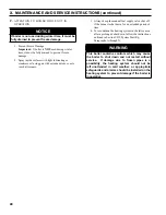
Cold Start Boiler Control
Adjustment mode Options
HL_
140-240°F
Adjust High Limit Setting
HdF
10-30°F
Adjust High Limit Differential
ZC_
dh
,
ZR
or
ELL
ZC and ZR Terminal Function
Or_
0-10 minutes
Pump Overrun Time
PP_
2-20 minutes
Pump Pre-purge Time
t_
140 - 180°F
Start Temperature
Pt_
On
or
Off
Priority Time
f-C
F
or
C
Select degrees F or C Mode
bac
Back to Operating Mode
Содержание LE DV Series
Страница 5: ...5 I General Information Figure 1A LEDV Packaged Water Boiler with Beckett AFII Burner ...
Страница 6: ...6 I General Information continued Figure 1B LEDV Packaged Water Boiler with Riello BF Burner ...
Страница 19: ...19 v venting continued Figure 11 Vent Installation Figure 12 Vent Connector Un Assembled ...
Страница 20: ...20 v venting continued Figure 13 Vent Connector Assembled Figure 14 Air Intake Installation ...
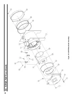
Страница 48: ...48 xiii Repair Parts continued Figure 29 LEDV Bare Boiler Assembly ...
Страница 50: ...50 xiii Repair Parts continued Figure 30 LEDV Boiler Jacket Insulation ...
Страница 55: ...55 xiii Repair Parts continued Figure 33 Vent Kit Repair Parts ...
Страница 60: ...60 U S Boiler Company Inc P O Box 3020 Lancaster PA 17604 1 888 432 8887 www usboiler net ...

