22
103448-10- 6/18
IV. Venting
B. CPVC/PVC Venting
Table 6: Vent/Combustion Air Equivalent Length Calculation Work Sheet
Component
Combustion Air
Vent
Equivalent
Length Per
Piece
X Quantity
=
Subtotal
Equivalent Length
Equivalent
Length
Per Piece
X Quantity =
Subtotal Equivalent
Length
Straight Pipe
X
=
A
E
90° Elbow,
Short Radius
X
=
B
F
90° Elbow,
Long Sweep/
Sanitary
X
=
C
G
45° Elbow
X
=
D
H
Combustion Air Total
Equivalent Length
=
A+B+C+D Vent Total Equivalent Length =
E+F+G+H
Notes:
1. Total equivalent length cannot exceed maximum equivalent length shown in Table 5A.
2. Use elbow equivalent lengths provided in Table 5B.
3. Combustion air and vent terminations do not count towards total equivalent length.
4. Pressure drop for flexible polypropylene liner is 20% greater than for rigid pipe. Multiply measured flexible polypropylene liner length by 1.2 to
obtain equivalent length.
Example
Measured length = 35 ft.
Equivalent length =35 ft. x 1.2 = 42 ft.
5. Maximum equivalent length of flexible polypropylene liner is 48 ft. (14.6 m).
Asphyxiation Hazard. Failure to follow these instructions could cause products of
combustion to enter the building, resulting in severe property damage, personal injury, or death.
Use all CPVC vent components (supplied with boiler) for near-boiler vent piping before transitioning to
Schedule 40 PVC pipe (ASTM 2665) components for remainder of vent system.
Use CPVC vent components within any interior space where air cannot circulate freely, including through
vertical or horizontal chase ways, inside a stud wall, in closets, and through wall penetrations.
The use of cellular core PVC (ASTM F891), cellular core CPVC or Radel (polyphenolsulfone) is prohibited.
All condensate that forms in the vent must be able to drain back to the boiler.
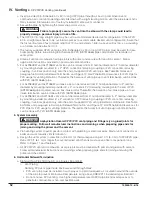
B. CPVC/PVC Venting
WARNING
NOTICE
Do not exceed maximum vent/combustion air system length. Refer to “2. Vent/Combustion Air
Piping” under “A. General Guidelines” of this section for maximum vent/combustion air system length.
Use only vent and combustion air terminals and terminal locations shown in “3. Vent/Combustion Air
Terminals” under “A. General Guidelines” of this section.
•
•
•
•
Содержание Alpine ALP080B
Страница 76: ...76 103448 10 6 18 VIII Electrical continued...
Страница 77: ...103448 10 6 18 77 VIII Electrical continued Figure 27 Wiring Connection Diagram...
Страница 78: ...78 103448 10 6 18 Figure 28 Ladder Diagram VIII Electrical continued...
Страница 82: ...82 103448 10 6 18 VIII Electrical continued Figure 29D Boiler to Boiler Communication with Zone Panel...
Страница 146: ...146 103448 10 6 18...
Страница 147: ...103448 10 6 18 147...
Страница 148: ...148 103448 10 6 18 U S Boiler Company Inc P O Box 3020 Lancaster PA 17604 1 888 432 8887 www usboiler net...


