u-line.com
27
Troubleshooting
Component Testing
NOTICE
Frequently toggling the compressor relay could force the
compressor into overload. The compressor will
automatically deactivate during an overload and will remain
deactivated until the overload switch cools, regardless of
relay and voltage state.
NOTICE
If the compressor is suspected of being faulty it is important
to verify all copper tubing, dryers, capillary lines,
evaporators and condensers are free from kinks, excessive
bends or blockages. A restriction in any of these
components would force the compressor to overload,
making it appear as if it is faulty.
If a component is suspected as being faulty, follow the
troubleshooting steps below to help isolate the cause.
1. Initiate Self Test Mode, address any current errors before
beginning component testing.
2. Activate the component’s relay or DC output through “Relay
Toggle” under the service menu.
3. Test for voltage at the component.
Voltage Present
If voltage is present and the component does not function, suspect a
faulty component. If the component being tested is the compressor,
make certain it is not overloaded by disconnecting power to the unit
for at least 15 minutes and re-testing.
No Voltage Present
If no voltage is present check for voltage at the relay / DC output.
Reference the diagram for component relay / DC output pins. If
voltage is present, suspect a faulty component cable. If voltage is not
present at the relay / DC output, cycle the power to the unit and
re-test. If voltage is still not present, suspect the main control of
being faulty.
Component Testing Example
Below is an example of how to properly test a component for
functionality. An evaporator fan is used.
Condition
Customer complains of the unit not cooling properly. The main
screen of the display lists an error “Temp Hi 12H+”. The compressor
seems to be functioning properly, however the evaporator fan does
not activate after a door cycle.
In the above case it would be wise to test the evaporator fan for
functionality.
Testing
1. Check “Self Test” for any additional errors that may be current.
2. Visually examine the fan through the fan cover. Note any ice
buildup. In this case no ice buildup was noticed. The fan appeared
as if it could spin freely.
3. Enter “Relay Toggle” and manually activate FAN1.
4. Check for fan operation. In this case the fan does not operate.
5. Remove the upper and lower back panel from the refrigeration
unit.
6. Ensuring the DC output is still active,
use a meter to check voltage at the fan
power connection point. In this instance
no voltage is present.
7. Ensuring the DC output is still active and
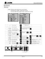
referencing the Connector & Pin ID
chart, a voltage test is performed across pins 1 and 6 of the header
labeled J4. In this case a stable 12 volts DC was noted.
8. Confirming that the board is sending voltage, the cabling between
the board and fan is inspected for damage. In this case some
damage is noted.
9. The fan cable harness is replaced, and the fan DC output is tested
again. It is noted the fan now spins freely.
10. The unit is then monitored for proper operation and any further
faults.
Relay Output
ID
Test
Point 1
Test
Point 2
Voltage
On
Voltage
Off
Comp
Pin J2-3
Pin J2-10
120
0
F-1
Pin J2-1
Pin J2-10
120
0
F-3 NA
---
---
---
---
L1
Pin J4-4
Pin J4-9
8-12 VDC
< 7 VDC
J2
J5
J4
J1
F1
J2
J4
J1
16
1
10
10
6
1
5
9
8
1
Connector & Pin ID
Voltage Checked
At Connection
J4
Voltage Checked
At These Pins

