2. Installation of the frequency converter
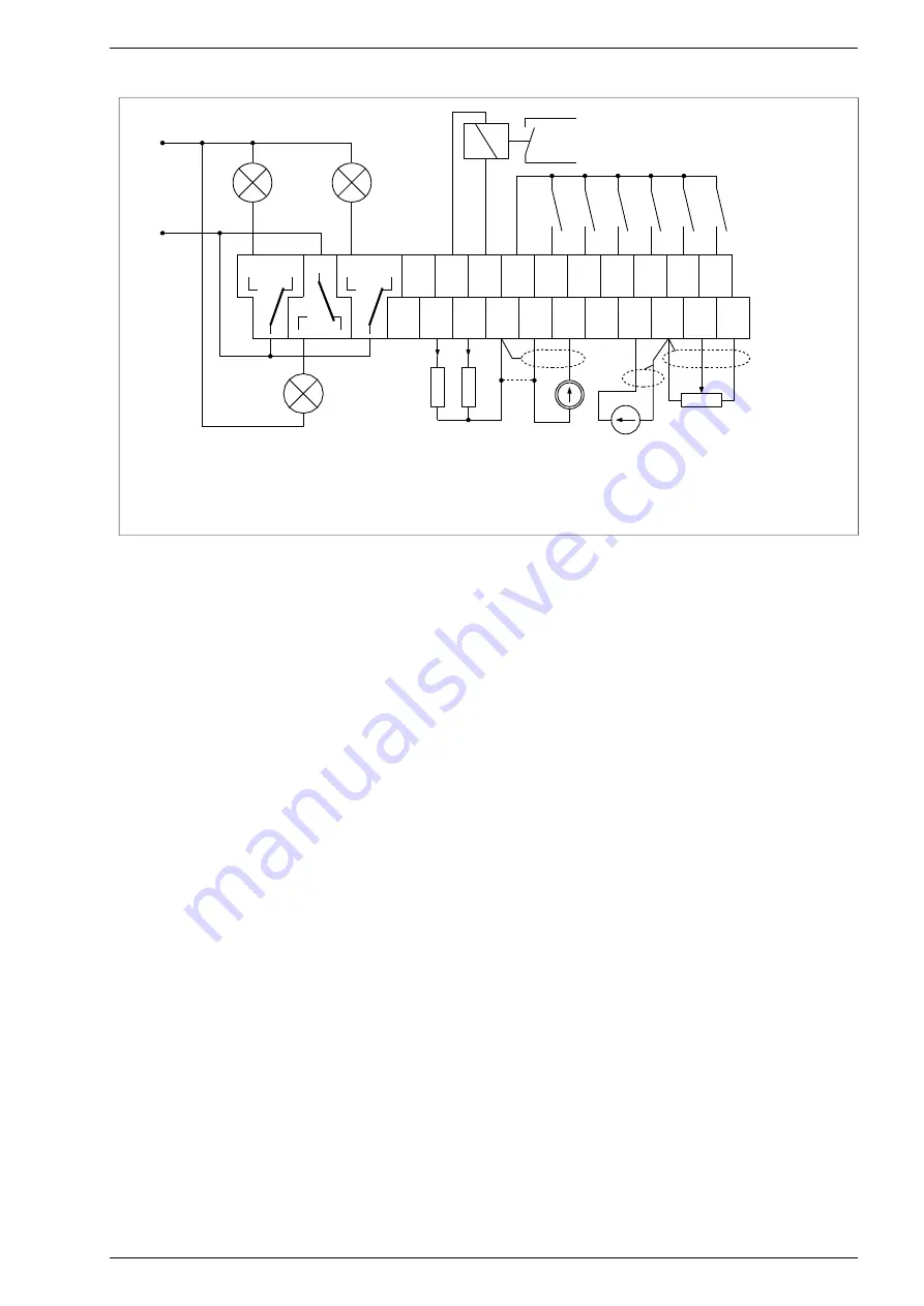
Fig. 2.7 shows an exemplary configuration of control circuit connections, based on the example of a terminal strip
of converters with a power of up to 18.5kW inclusive.
Fig. 2.7 - Example configuration of frequency converter terminal connections for MFC710 18,5kW and below.
Uref = 10 Vdc, max 10 mA.
2.3. Using contactors between the frequency converter and the electric motor
If there is a need to use contactors between the drive and the electric motor, make sure to switch the contactor
in the voltageless state on the output terminals, when the drive is stopped (STOP status). Otherwise there is a high
probability of damaging the converter.
Attention:
Just issuing the STOP command is not sufficient, because there is a possibility of programmatic
delay of the response to the STOP command (par. 1.34) and the possibility of setting a stop on a ramp (par. 1.64).
For this reason, in order to avoid damage to the converter, it is necessary to control the OPERATING status of
the converter (PCH.61), e.g. by using one of the relays. The default setting of the K2 relay (par. 2.92, 2.93) is suitable
for this purpose.
Frequency converter MFC710 type with OP-11 control panel. TWERD Power Electronics
19
24
V
A
O
1
A
O
2
D
O
4
24
V
G
N
D
K2
K1
K3
-A
I1
D
I1
D
I2
D
I3
D
I4
D
I5
D
I6
G
N
D
A
I0
U
re
f
Digital inputs
DI1...DI6
0V = logic „0”
24V = logic „1”
External relay control via DO4
Output type: open collector U
MAX
=24V,
I
MAX
=100mA
230V AC
Relay outputs can be applicated to control
power supply of 230V devices.
K1, K2, K3 Relays
Potentiometer connected
to AI0 (operates in voltage
mode only)
AI1 in current
mode
0(4)...20mA
AO2 in current mode
0(4)...20mA R
L
< 1kΩ
AO1 in voltage mode
0(2)...10V R
L
> 10kΩ
R
L
<
1
kΩ
AI2 in voltage
mode
0(2)...10V
R
L
>
1
0k
Ω
+
A
I1
-A
I2
+
A
I2
250V/1A AC
24V/1A DC


