35
10. MODEL 7000C SERIES DISASSEMBLY AND REASSEMBLY
WARNING
Before performing any repair or replacement, disconnect and lock out
power.
With proper maintenance and lubrication, normal life expectancy for gears, bearings, and seals can
be achieved. However, over a period of time these parts must be repaired or replaced to maintain the
efficiency of your booster. This section is written in a way that will allow you to completely disassemble your
booster. The inspection of certain repairable or replaceable parts is referred to at the point of disassembly
where these parts are exposed. If at any point of inspection, repair or replacement is deemed necessary,
appropriate instruction will be given to achieve these repairs or replacements is deemed necessary,
appropriate instruction will be given to achieve these repairs or replacements.
10.1 DISASSEMBLY OF 7000C SERIES BOOSTERS
1. Remove unit from
installation and drain
lubricant from both ends
by removing magnetic
drain plugs (31). Mark
end plates, covers and
housing so they can be
reassembled in their
original position.
2. Remove motor, coupling
and C-flange adapter.
3. Remove four socket head
screws (93). Requires
5/32” hex head (Allen)
wrench. Place two of the screws in tapped jacking holes and remove seal housing (91). Tap out seal
and discard O-rings.
4. Remove gear cover cap screws (26) and gear cover (6) by placing two of the screws in the tapped
jacking holes provided on the cover flange. Support cover with lift straps or other suitable means while
removing. The jackscrews will provide the force necessary to break the seal between cover and end
plate.
5. Temporarily secure end plate to housing with two screws (26) and some flat washers. Remove four
nylok screws (66) from drive shaft (45). A light tap with a mallet will break it loose from the gear.
Remove mating ring of mechanical seal [54].
6. Bend back lock tabs and remove cap screws (29), lock (59), washers (25) and spring pins (68).
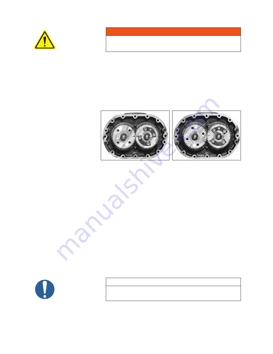
7. Position timing gears (8) so both timing marks are matched. See Figure 16. Rotate drive gear clockwise
approximately three teeth and mark a matching reference line on each gear as shown in Figure 17.
This gear position is necessary so rotors will clear and not jam. Using a gear puller with a live center or
a centering adapter, large enough so it will not jam into threaded hole, pull driven gear, while keeping
matched reference line marks aligned. Use a slight rocking motion to insure rotors have not jammed.
Should jamming occur, release pressure and tap gear back on until it rotates freely. Pull mating gear.
NOTE
Never attempt to pull gear when rotors are jammed. Rotor keyway damage
will result.
Figure 16 - Position of timing marks
Keyways in line
and timing marks matched
Figure 17 - Position of timing marks
Timing marks advanced 3 teeth and
reference marks aligned.
Содержание M-D Pneumatics 7010
Страница 43: ...43 NOTES ...
Страница 50: ...50 3200C CUTAWAY DRAWING 3200 90C 91C 92C 93C 1 OF 2 A ...
Страница 51: ...51 3200C CONFIGURATIONS DRAWINGS 3200 90C 91C 92C 93C 2 of 2 A ...
Страница 54: ...54 5500C CUTAWAY DRAWING 5500 90C 91C 92C 93C 1 OF 2 E OIL LEVEL SIGHT GAUGE DETAIL ...
Страница 55: ...55 5500C CONFIGURATIONS DRAWINGS 5500 90C 91C 92C 93C 2 of 2 E ...
Страница 56: ...56 7000C CUTAWAY DRAWING 7000 90C 91C 1 OF 3 ...
Страница 57: ...57 7000C CONFIGURATIONS DRAWING 7000 90C 2 OF 3 ...
Страница 58: ...58 7000C CONFIGURATIONS DRAWING 7000 91C 3 OF 3 7000 91C 7013 SHOWN ...
Страница 68: ...68 NOTES ...


