background image

6

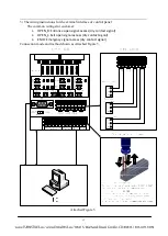
11) Screw the nuts after all equipment has been tested to work well.

Notice: 

1. The depth of the PVC tubes buried shall be more than 60mm. The height above the
ground shall be more than 50mm. And the exit of the PVC tube shall be bent return so
as to avoid the water falls in.
2. All the above steps shall be operated under the condition of power off and make sure
that the system protection ground cable is connected.
3. If the equipment is used outdoors, please build a cement platform for the equipment
with the height of 100mm---200mm to resist humidity. Meanwhile, an awning or other
facility is needed to resist rain. It’s forbidden to use the equipment directly in the open
air.

5.2 Equipment Functional Test 

The  operating  procedure  is  shown  below  and  given  the  sequence  of  passage  through  the 
turnstile  in  either  direction.  The  barrier  swing  will  normally  be  locked,  unless  a  free 
entry/exit  option  has  been  specified  operate  the  Access  Control  Device  if  fitted.  On  the 
acceptance of a signal from the Access Control Device the barrier swing rotate to 90° for 
unlocking, After the pre-set time, the main controller controls the motor drives the barrier 
rotate to the limit position and lock automatically, the counter will automatically increase 1 
at  the  passing  direction.  Go  signal  will  be cancelled  if passage  through  is  not  completed 
within  pre-set  time.  The  standard  default  is  5  seconds.  The  user  may  carry  out  one  or 
several functional tests as given below in accordance with the requirements on the passage 
function of the turnstile. 

5.2.1 Single time card reading passage: 

When the passenger read an effective card, the main controller electrifies the barrier swing 
rotate to 90° for unlocking, After the pre-set time, the main controller controls the motor 
drives  the  barrier  rotate  to  the  limit  position  and  lock  automatically,  the  counter  will 
automatically  increase  1  at  the  passing  direction.  Go  signal  will  be  cancelled  if  passage 
through is not completed within pre-set time (the default pre-set time being 5s). 

5.3.2 Function of barrier swing open at power off 

The barrier swing should be open automatically when the power of the system is cut off 

5.3.3 Far end control 

The  following  setting  and  test  should  be  carried  out  when  the  management  computer  is 
used for far end control of the barrier swing. 

Содержание TPW-321ASP

Страница 1: ...OPERATING MANUAL AUTOMATIC SWING GATE TPW 321ASP...

Страница 2: ...4 3 SYSTEM COMPOSITION 4 5 EQUIPMENT ASSEMBLY AND INSTALLATION 4 5 1 EQUIPMENT INSTALLATION 4 5 2 EQUIPMENT FUNCTIONAL TEST 6 5 3 3 FAR END CONTROL 6 6 OPERATION INSTRUCTION OF THE EQUIPMENT 7 7 REGU...

Страница 3: ...the system It is recommended that the user read carefully the operation manual prior to application of the equipment otherwise your right may be infringed due to an improper application of the equipme...

Страница 4: ...ctro mechanism mounted within the top section of the Automatic Swing Gate and accessible by open the Top Cover Purely mechanical control is also possible 8 It is provided with multiple operation modes...

Страница 5: ...des there are also different types and specifications depending on different read write equipment installed 1200 Figure 1 4 Basic Operation Principle 4 1 Basic Operation Principle When card in card ou...

Страница 6: ...ay flow limit 2 One way reading card the other way barring 4 3 System Composition The product can either be used independently to form a passage or be combined into multiple passages of intelligent ma...

Страница 7: ...undation Drawing for Ground Installation 5 Pull the cable of the heavy current light current through the 3 4 PVC tubes respectively and bury them into the relevant position with cement 6 Move the equi...

Страница 8: ...for unlocking After the pre set time the main controller controls the motor drives the barrier rotate to the limit position and lock automatically the counter will automatically increase 1 at the pass...

Страница 9: ...a green lamp Otherwise the normal operation of equipment may be affected 6 3 It is forbidden to sit or press with force on the barrier rod when the equipment is not in use otherwise the turnstile may...

Страница 10: ...ection grounding of the system to ensure a reliable connection 4 It is required to check regularly the connectors and line connection points to ensure a reliable connection 8 Common Failures and the R...

Страница 11: ...nd sound alarm if passengers get into the gate area without sign in sign out NC mode normal close gate stay in close state gate will open if passenger sign in sign out successfully gate will return to...

Страница 12: ...oor closing time setting the max time for each passenger entering the passage The value effective range is 1 60 unit is second Default 5 4 Entry counter reset clear entry counting value 5 Exit counter...

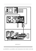
Страница 13: ...11 Attached Figure 4...

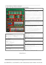
Страница 14: ...12 2 The instructions of turnstile control panel Turnstile control panel instructions shown as Attached Figure 4 Attached Figure 4...

Страница 15: ...panel The common wirings for customer 1 OPEN_R Entrance open signal access dry contact signal 2 OPEN_L Exit open signal access dry contact signal 3 EMO Emergency signal access dry contact signal Conne...

Страница 16: ...ertime waiting time is 2 seconds The control board of turnstiles will send related parameters after received feedback signal Every parameter sent by main board needs the feedback signal address if you...

Страница 17: ...l board successfully corresponding commands can be sent to the control board to set the parameters The control board will send success return signal 0x02 0x44 0x00 0x04 to PC if the setting is success...

Страница 18: ...c tripod turnstiles For detailed command formats please refer to 3 Control Board Receiving Command Below is the flow Chart 2 Control Board Sending Command Control Board Sending Command Format Command...

Страница 19: ...tatus the second word shows exit status 0x30 Controlled Mode 0x31 Free Passing Mode 0x32 Forbidden Passing 0x33 Barrier free passing after swiping card 0x18 0x03 0x30 0x39 0x30 0x39 0x30 0x39 Door clo...

Страница 20: ...x33 Setting working mode of entry exit the first word shows setting entry working mode the second word shows setting exit working mode 0x30 Controlled Mode 0x31 Free Passing Mode 0x32 Forbidden Passin...

Страница 21: ...counting see the sending command format table 0x42 0x01 0x31 0x37 Setting the door opening closing speed ranking 1 7 0x31 0x37 ASCII code of 1 7 inapplicable to tripod turnstiles 0x81 0x01 0x31 0x35...

Страница 22: ...is command the control panel will set the display image of LED panel on both sides according to the command contents and then return to the feedback command The first word refers to LED panel address...

Отзывы:

Похожие инструкции для TPW-321ASP