5
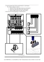
2) After making sure of the system constitution and working principles, please make an
overall plan to be ready for the installation.
3) Please arrange the equipment in order after neatening the ground surface.
4) After fixing the positions of the holes, drill and pre-embed the ground bolt or the
expansion bolt of M12.
M12
Concrete 525#
Expansion Bolt
Ground Foot Installation Foundation Drawing
10
0
Installation Diagram of Automatic Swing Gate
T
PW-321ASP01
135°
135°
II
III
12
00
915
915
φ168
φ168
φ168
φ168
φ168
φ168
810
810
1001
1083
1199
1001
1083
1199
896
978
1094
896
978
1094
82
II
III
24-Ø16Use expansion bolts
(M12*100mm)to fix with ground
8-
φ
50 Cable hole
Fig.3 Foundation Drawing for Ground Installation
5) Pull the cable of the heavy current & light current through the 3/4’’ PVC tubes
respectively; and bury them into the relevant position with cement.
6) Move the equipment to the corresponding installation position and aim at the ground
bolt one by one first.
7) Check whether the system constitution and working mode is correct before
proceeding to next step.
8) Open the door of the equipment case, choose one of the equipment to be the
reference standard. Make the bolt hole of the equipment foundation aim at the ground
bolt, and pre-fasten the nut.
9) Open the door of the neighboring equipment. Make the bolt hole of the equipment
foundation aim at the ground bolt, and pre-fasten the nut. Any more equipment just
needs to be installed analogically.
10) Connect the power cable, control cable and the system protection ground cable.
Содержание TPW-321ASP
Страница 1: ...OPERATING MANUAL AUTOMATIC SWING GATE TPW 321ASP...
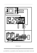
Страница 13: ...11 Attached Figure 4...


