4
TBV123 / TBV123-AN and TBV118L / TBV118L-AN Rigging Manual
Chapter 1: Safety Information
1.1 Intended Use
The rigging components (TBV123-FB flybar, rigging pins, mounting links) shall only be used in conjunction with TURBOSOUND TBV123, TBV123-AN loudspeakers and
TBV118L and TBV118L-AN subwoofers as described in this manual.
NOTE: Throughout this manual, and unless otherwise noted, the term "TBV123" refers to the TBV123 passive loudspeaker or the TBV123-AN powered loudspeaker.
These speakers share identical cabinet dimensions and rigging points. The term "TBV118L" refers to the TB118L passive subwoofer, or the TBV118L-AN powered
subwoofer. These subwoofers share identical cabinet dimensions and rigging points.
1.2 Intended Use of this Manual
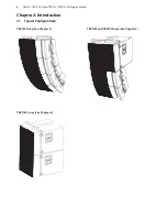
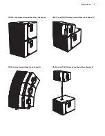
The instructions in this manual describe how to assemble various configurations of TBV123 loudspeaker cabinets, TBV118L subwoofers, and the TBV123-FB flybar,
in readiness for suspending or ground stacking.
These instructions shall only be used with the TURBOSOUND TBV123, TBV123-AN, TBV118L, TBV118L-AN, and TBV123-FB components.
The instructions do not show details of external lifting equipment, and do not contain details of safe lifting procedures or installation.
Possession of these instructions and procedures does not imply authorisation for their use.
1.3 General Safety
The operation of your product as part of a suspended system, if installed incorrectly and improperly, can potentially expose persons to
serious health risks and even death.
In addition, please ensure that electrical, mechanical and acoustic considerations are discussed with qualified and certified (by local, state or national authorities)
personnel prior to any installation.
Installation and setup should only be carried out by qualified and authorised personnel observing the valid local, state and other safety regulations applicable in your
country. If any parts or components are missing please contact your dealer before attempting to set up the system.
It is the responsibility of the person installing the assembly to ensure that the suspension/fixing points are suitable for the intended use.
We also recommend you schedule TURBOSOUND line array training with our sales partners and applications team.
Equipment used to connect to the TURBOSOUND rigging system must be properly rated and must conform to the local, state and other safety regulations. Do not use
TURBOSOUND rigging with other types or brands of loudspeakers. This practice may compromise safety standards and MUSIC Group will not be responsible for damage
or injury so caused. Do not modify the rigging accessories, or use them in a way other than that described in this rigging manual. Rigging components supplied as part
of a complete assembly are non-interchangeable and must not be exchanged with the component parts of any other assembly.
Welding, or any other means of permanently fixing rigging components to each other or to cabinet fixing points is not allowed. Rigging components or assemblies
must only be fixed to TURBOSOUND loudspeaker cabinets using the cabinet fixing points.
MUSIC Group assumes no liability for any damage or personal injury resulting from improper use, installation or operation of the product. Regular checks must be
conducted by qualified personnel to ensure that the system remains in a secure and stable condition. Make sure that, where the product is suspended, the area
underneath the product is free of human traffic. Do not suspend the product in areas which can be entered or used by members of the public.
1.4 Loudspeaker Cabling
Attach and support the speaker cables from your amplifiers to the loudspeaker cabinets, so that no significant additional weight or lateral force is applied to the array
by the input wiring.
Input cables or link cables should never be used to angle the array or used as rigging in any way.
1.5 Load Capacity and System Safety
The TBV123-FB flybar is designed to suspend a maximum of 4 TBV123 loudspeaker cabinets, or 2 TBV118L subwoofers, or a mixed array of 1 TBV118L subwoofer with
2 TBV123 loudspeaker cabinets. The speakers may be flown with any vertical splay angle configuration and from any of the pick points. This corresponds to a Working
Load Limit (WLL) of 100 kg with a design factor of 10:1.
TBV installation procedures and recommendations described in Chapters 3-5 are based on 10:1 design factor. TBV enclosure counts and combinations are also given for
5:1 and 7:1 design factors in Chapter 13. Check local regulations in order to comply with regional design factor requirements. Always refer to EASE FOCUS II modeling
software error and warning indications prior to installation.
Содержание TBV118L-AN
Страница 50: ......


