Page 20
Maintenance
Tsurumi’s Operation, Service, and Repair Manual
4-8 Removal and Installation of Engine
A.
If you need to remove or replace engine (33) to access cushions (23 or 24), proceed as fol-
lows:
(1)
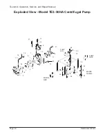
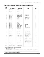
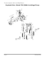
Refer to exploded view in
REPLACEMENT PARTS
section for parts location. Remove
nuts (26 and 27). Lift engine (33) off threads of cushions (23 and 24) in frame (21).
(2)
Check condition of cushions (23 and 24). Replace any damaged cushions.
(3) Position frame (21) so the engine (33) is in normal operating position (with fuel tank up).
(4)
Remove two nuts (26) from cushions (24) in mounting flange of engine (33).
(5)
Lift engine from threaded ends of cushions (24).
(6) Align holes in mounting flange of replacement engine over the threaded ends of the
cushions (24).
B.
Assemble remaining components according to the instructions in
4-11. Assembly of
Centrifugal Pump.
4-9 Replacement of Cushions
NOTE:
•
Use wooden blocks to support the centrifugal pump frame during disassembly and assembly.
•
Refer to Figure 4-4 for location of
parts used on Models TE
3
-50HA and TE
3
-80A.
A.
Replacement of
Pump Cushions (24) on Models TE3-50HA and TE3-80A.
(1)
Remove screws (30) from casing (2) and brackets (25).
(2)
Remove nuts (27) and brackets (25) from threaded end of cushions (24).
(3) Remove nuts (26) from threaded end of cushion (24) (on the underside of frame
crossover support). Remove cushions and check for damage; replace damaged
cushions.
(4) Install threaded end of new cushions (24) through holes at pump end of frame.
Secure with nuts.
(5)
Install short end of new cushions (23) through holes at engine end of frame. Secure
with nuts (26).
NOTE:
•
Refer to Figure 4-9 for location of
parts used on Models TE
3
-100HA.
B.
Replacement of
Engine Cushions (23) on Model TE3-100HA.
(1) Remove
pump components according to the instructions in
4-11. Remove
Centrifugal Pump.


