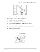
(2)
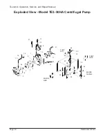
Remove nuts (26) and bolts (28) from base (22). Remove engine (33) from base (22).
(3)
Remove nuts (26) from threaded ends of cushions (23).
(4)
Lift the base (22) from cushions (23).
(5) Remove nuts (26) from underside of frame (22) and check cushions for damage.
Replace damaged cushions.
(6) Install threaded end of new cushions (23) through holes at pump end of frame (21).
Secure with nuts (26).
(7)
Install short end of new cushions (23) through holes at engine end of frame. Secure
with nuts (26).
CAUTION:
•
MAKE SURE YOU CHECK TIGHTNESS OF THE FOUR NUTS (26) ON THE UNDERSIDE OF
THE FRAME. TIGHTENING THE NUTS ON THE TOP SIDE OF THE FRAME MAY LOOSEN
THE NUTS ON THE UNDERSIDE OF THE FRAME.
(8)
Install base (22) over the long threaded ends of cushions (23). Tighten nuts (23).
(9)
Install engine (33) on base (22). Align boltholes in flange of engine (33) with holes in
base (22).
Maintenance
Page 21
Tsurumi’s Operation, Service, and Repair Manual
23
ENGINE
MOUNTING
FLANGE
PUMP
SIDE
ENGINE
SIDE
26
26
21
28
23
22
26
29
26
26
30
35
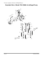
Figure 4-9: Exploded View for Frame and Base of Model TE
3
-100HA Pump

