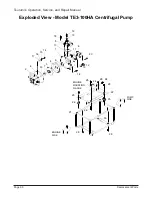
(10) Install bolts (28) from underside of base (22) through holes in engine mounting flange
and secure with nuts (29).
(11) Install remaining components. Refer to
Assembly of Centrifugal Pump
for installa-
tion procedures.
4-10 Assembly of Centrifugal Pump
WARNING:
•
THE SHIPPING WEGHT OF THE MODEL TE2-SERIES PUMPS RANGE FROM 55 TO 109
POUNDS. TO AVOID PERSONAL INJURY, USE AN OVERHEAD LIFTING DEVICE OR GAIN
THE ASSISTANCE OF ANOTHER PERSON TO LIFT THE PUMP ON AND OFF THE BENCH.
•
IT IS RECOMMENDED THAT THE PUMP BE ASSEMBLED AND DISASSEMBLED ON A
BENCH OR SIMILAR STRUCTURE WITH THE ENGINE SHROUD FACING DOWN. IN ADDI-
TION, WOODEN BLOCKS IN A VARIETY OF LENGTHS AND THICKNESS SHOULD BE
AVAILABLE FOR SUPPORT OF THE ENGINE AFTER PUMP REMOVAL.
NOTE:
•
Separate parts listings are provided for each model of centrifugal pump. Make sure you order
parts from the listing for your model of centrifugal pump (the model number is provided on the
pump nameplate).
•
Use wooden blocks to steady and support the frame (21), the pump, and the engine (33) during
disassembly and assembly.
•
These procedures assume that the engine is installed.
•
Installation instructions for mechanical seal (7) are contained in
4-7. Replacement of
Mechanical Seal.
A.
Position frame (21) with the engine (33) in normal operating position (with fuel tank up).
B.
Make sure the fixed element of mechanical seal (7) is installed in casing cover (2).
C.
Make sure the rotating element of mechanical seal (7) is installed in impeller (3). (The
rotating element of the mechanical seal consists of the rubber cushion and mating ring.)
D.
Position casing cover (2) against the engine with the center bore cutout in casing cover (2)
facing downward at the bottom of the frame.
E.
Install bolts (14), spring washers (15), plain washers (16), and seals (17) in holes in casing
cover (2). Replace seals (17) if damaged.
F.
Install O-ring (8) on casing cover (2).
G.
If a new mechanical seal has been installed, take measurements and select shims required
to provide clearance between the impeller (3) and the casing cover (2). Refer to
Replacement of Mechanical Seal
for shim measurement procedures.
H.
Install shim (31) in bore of impeller (3).
Page 22
Introduction
Tsurumi’s Operation, Service, and Repair Manual


