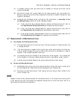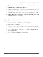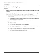
Page 18
Maintenance
Tsurumi’s Operation, Service, and Repair Manual
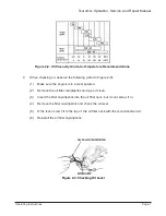
LEGEND
A
=
B + C (Tool length)
B
=
Overall uninstalled height of mechanical seal.
C
=
Length of casing cover center bore from start of bore to face of installed seal. Multiply
length times 2.
D
=
Outside diameter of tool to have a slip fit with inside diameter of mechanical seal.
E
=
Inside diameter of recess to be sized to fit over the mechanical seal. Recess depth to
be enough to contact only the cup flange of the mechanical seal.
F
=
Outside diameter to be same diameter as the cup flange on mechanical seal.
(The outside diameter of the tool should be sized to have a slip fit with the center bore
of the casing cover (2). The inside diameter of the tool should be sized so the tool
contacts the metal cup of the seal.)
Figure 4-5: Mechanical Seal Installation/Removal Tool
(3)
Clean bore in casing cover to remove all traces of sealant residue.
(4) Take the measurements needed for calculating the thickness of shim (31). The
shim is sized to provide clearance between the casing cover (2) and impeller (3).
(a)
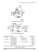
Refer to Figures 4-6. Measure and record dimension A.
(b)
Refer to Figures 4-7. Measure and record dimension B.
(c)
Subtract dimension B from dimension A. The resultant dimension is the
thickness of the shim (31).
A
____________
Minus B
____________
=
____________
(
Depth of Volute Casing)
(Height of Installed Impeller)
(Shim Thickness)
(5)
Select the combination of shims (31) (see Figure 4-8) that will provide clearance
of 0.020 inch to 0.040 inch (0.508 mm to 1.016 mm). Temporarily set shims (31)
aside for installation later.
(6) Complete assembly of the centrifugal pump according to the procedures in
Assembly of the Centrifugal Pump.
A
D
F
E
B
C


