


MDC General Information
In difference to other controls the MDC provides a mechanical deadband. This is required to overcome
the tolerances in the mechanical actuation.
The MDC contains an internal end stop to prevent over travel. The restoring moment is appropriate for
turning the MDC input shaft back to neutral only. Any linkages or cables may prevent the MDC from
returning to neutral.
The MDC is designed for a maximum case pressure of 5 bar and a rated case pressure of 3 bar. If the case
pressure exceeds 5 bar there is a risk of an insufficient restoring moment. In addition a high case pressure
can cause the NSS to indicate that the control is not in neutral. High case pressure may cause excessive
wear.
Customers can apply their own handle design but they must care about a robust clamping connection
between their handle and the control shaft and avoid overload of the shaft.
Customers can connect two MDC’s on a tandem unit in such a way that the actuation force will be
transferred from the pilot control to the second control but the kinematic of the linkages must ensure
that either control shaft is protected from torque overload. To avoid an overload of the MDC, customers
must install any support to limit the setting range of the Bowden cable.
C
Caution
Using the internal spring force on the input shaft is not an appropriate way to return the customer
connection linkage to neutral.
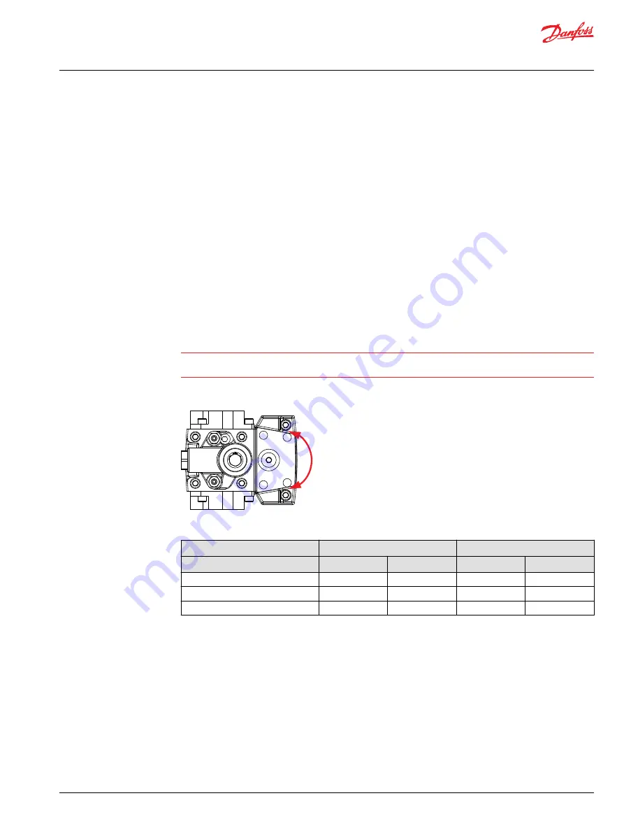
MDC Shaft Rotation
CCW
CW
P301 753
MDC shaft rotation data
Pump shaft rotation
*
Clock Wise (CW)
Counter Clock Wise (CCW)
MDC shaft rotation
CW
CCW
CW
CCW
Port A
in (low)
out (high)
out (high)
in (low)
Port B
out (high)
in (low)
in (low)
out (high)
Servo port high pressure
M5
M4
M5
M4
*
As seen from shaft side.
Control Response
MP1 controls are available with optional control passage orifices to assist in matching the rate of
swashplate response to the application requirements. The time required for the pump output flow to
change from zero to full flow (acceleration) or full flow to zero (deceleration) is a net function of spool
porting, orifices, and charge pressure. A swashplate response table is available for each frame indicating
available swashplate response times. Testing should be conducted to verify the proper orifice selection
for the desired response.
Service Manual
MP1
Operation
©
Danfoss | July 2017
AX00000244en-US0103 | 21
Содержание DP20-4H
Страница 11: ......
Страница 12: ......
Страница 26: ......
Страница 27: ......
Страница 28: ......
Страница 29: ......
Страница 30: ......
Страница 31: ......
Страница 32: ......
Страница 33: ......
Страница 34: ......
Страница 35: ...Service Manual Variable Displacement Pumps MP1 powersolutions danfoss com ...
Страница 93: ...Service Manual MP1 Danfoss July 2017 AX00000244en US0103 59 ...
Страница 94: ...Service Manual MP1 60 Danfoss July 2017 AX00000244en US0103 ...
Страница 95: ...Service Manual MP1 Danfoss July 2017 AX00000244en US0103 61 ...
Страница 110: ......
Страница 111: ......
Страница 112: ......
Страница 113: ......
Страница 115: ......
Страница 154: ......
Страница 156: ...www dexteraxle com OPERATION MAINTENANCE SERVICE MANUAL 600 8 000 lb Axles Related Components ...
Страница 238: ...Service Record Date Service Performed Mileage ...
Страница 239: ...Service Record Date Service Performed Mileage ...
Страница 240: ...Service Record Date Service Performed Mileage ...


