TSE DP20-4H Скачать руководство пользователя страница 137

22

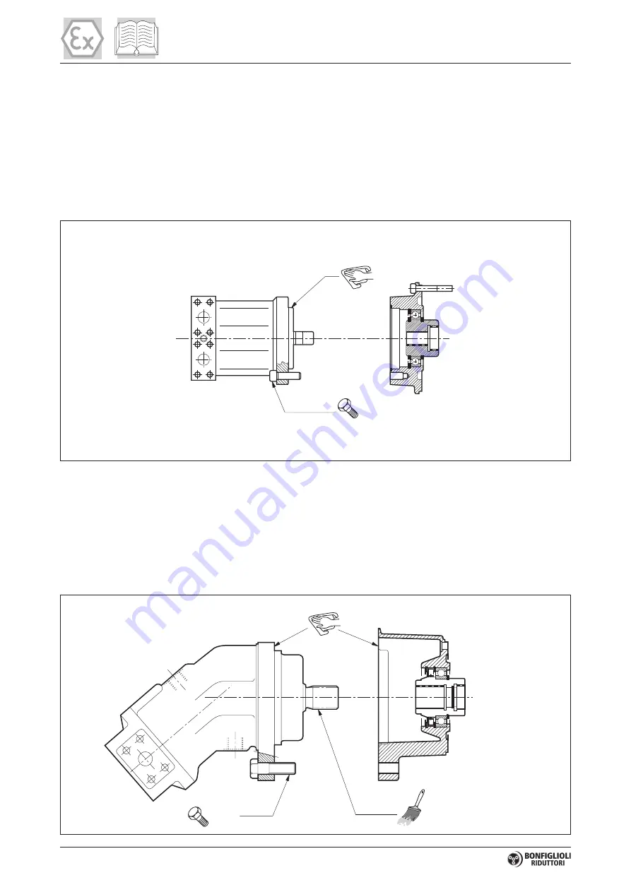
5.3 - INSTALLING THE HYDRAULIC MOTOR

Connecting the hydraulic motor

Remove the protective plug.
Hydraulic motor mountings are available in two versions:

a) Version with O-ring oil gasket between motor flange and gear unit.

In this case, mount the gasket to ensure an oil tight seal between the motor and gear unit, taking care to fit it
correctly in its seat without damaging it.

³

 8.8

b) Version with gasket already mounted to the coupling.

In this case no special intervention is required to ensure an oil tight seal since this is already provided by the
motor coupling. Merely smear the motor shaft with grease.
In both cases, clean the spigot and the coupling where the motor is to be fitted, fit the motor and tighten
down the flange mounting bolts.
Always use bolts rated to at least class 8.8.

³

 8.8

Содержание DP20-4H

Страница 1: ...www tse international com 5301 Shreveport Blanchard Hwy Shreveport Louisiana 71107 USA P 318 929 2368 F 318 929 4853 Owner s Manual Model DP20 4H Drum Puller Serial Number 18 5048 01 ...

Страница 2: ... the conductor towers and hardware The central operator s console allows the operator to completely control the pulling operation with optimum visibilty of the pulling rope Operator controls include linepull linespeed holding brake and engine controls DIMENSIONS WEIGHT APPROX Length 15 Width 8 Height 6 4 Weight 7 820 lbs with rope STANDARD FEATURES 2 000 lb linepull capacity on single full drum of...

Страница 3: ...e to be returned prepaid to TSE Items not returned within 30 days will result in the RGA closure and may result in a denial of the claim 3 Warranty submission must be on the standard TSE International Inc claim form Claims that are not will be classified as pending until proper forms are submitted All claims must have an estimated cost associated with each item under discrepancy 4 Major subcompone...

Страница 4: ...dual application of the equipment described in this manual The contents of this manual are intended as a basis of for operation maintenance and parts listing of the unit in its intended and anticipated use as it stands alone in conjunction with other equipment The Equipment described in this manual is potentially dangerous if improperly or carelessly operated For the protection of personnel and eq...

Страница 5: ...ts innovative products with Premium Customer Service Our comprehensive Service Department provides TSE customers with the service parts and technical assistance they need to maintain their equipment in top operating condition For Customer Service on Your Model Serial No PLEASE CALL 1 800 825 2402 Our People Care Our Equipment is the Proof 18 5048 01 DP20 4H ...

Страница 6: ...der the replacement part locate the part from the drawings in this manual and give the following information 1 Unit Model No From the plates on the unit s frame 2 Unit Serial No From the plate on the unit s frame will contain numbers only 3 Part Number If available 4 Description If part no not available 5 Quantity Required On large components such as transmissions engines multiple pump drives etc ...

Страница 7: ...y trained operators who are critically aware of the proper procedures operating parameters and limitations potential dangers and application of this equipment should be allowed to touch the controls at any time There is potential DANGER of ELECTRICAL SHOCK when operating this machine Ground the unit in accordance with the regulations of the using organization Various methods of bonding isolation a...

Страница 8: ...which after shipment from the factory of TSE has not been altered changed repaired or treated in any manner whatsoever unless such alteration change repair or treatment has been previously authorized in writing by TSE or has been performed by the authorized service representative of TSE This Warranty to repair is the only Warranty either express implied or statutory upon which the said machinery i...

Страница 9: ...THODS Grounding Equipment and Methods information is covered in the following publication IEEE GUIDE TO INSTALLATION OF OVERHEAD TRANSMISSION LINE CONDUCTORS IEEE STD 524 2003 The above publication is available through the following organization THE INSTITUTE OF ELECTRICAL AND ELECTRONICS ENGINEERS INC 3 PARK AVENUE NEW YORK NY 10016 5997 USA ...

Страница 10: ...hese decals be missing they could prevent the proper operation and or maintenance of the unit which may result in personal injury or property damage If any of these decals are missing please contact us for a replacement Order the decal s by stating the decal description number and quantity TSE INTERNATIONAL 5301 SHREVEPORT BLANCHARD HWY SHREVEPORT LA 71107 ATTENTION SERVICE MANAGER TELEPHONE 800 8...

Страница 11: ......

Страница 12: ......

Страница 13: ... ASSEMBLY DP20 4H 8602356 B GENERAL ASSEMBLY DP20 4H Yanmar Engine 861207 I REELS SHAFT ASSEMBLY 780101 C DRIVE ASSEMBLY 7601293 A HYDRAULIC SCHEMATIC 7601116 C TRAILER LIGHTING DIAGRAM LED 7601328 A ENGINE PUMP ASSEMBLY 7601331 CONTROL PANEL ASSEMBLY SECTION V VENDOR INFORMATION ENGINE Yanmar PUMP MOTOR BRAKE GEARBOX AXLE ...

Страница 14: ... SIGN APPEARS ON THESE PAGES IT INDICATES WHERE SPECIAL ATTENTION SHOULD BE PAID TO THE INSTRUCTIONS GIVEN PERSONAL INJURY OR DAMAGE TO THE EQUIPMENT MAY OCCUR IF THE INSTRUCTIONS ARE NOT FOLLOWED DIMENSIONS Length 186 inches Width 96 inches Height 104 inches Top of Operator Screen PERFORMANCE 1 Full Reel 2 000 lbs 3 5 MPH 4 Reels Simultaneously 500 lbs 2 0 MPH Speed Range 0 4 mph WARNING THESE VA...

Страница 15: ...ed 3000 psi during the operation of the machine 2 Linepull Control The pressure in the hydraulic system is regulated with this control knob also shown in Figure 2 Clockwise rotation of the Linepull Control increases pressure and therefore increases the Linepull Counter clockwise rotation of the Linepull Control decreases pressure and therefore decreases the Linepull Once the system pressure is set...

Страница 16: ...ERIFIED BEFORE THE UNIT IS PUT INTO SERVICE TO ENSURE SAFE OPERATION THIS IS PARTICULARLY IMPORTANT WHEN STRINGING IN THE VICINITY OF ENERGIZED LINES Figure 3 Brake Control 4 Direction Control The reel turning speed Linespeed and direction is controlled by a single lever that regulates the degree of pump stroke in both directions from the NEUTRAL Position also shown in Figure 4 Movement of the Dir...

Страница 17: ...ive screen is folded down 3 Wheel brakes are operational 4 Tires are inflated to proper pressure 5 Wheel chocks are removed and stored away properly 6 Lights are operational 7 All reel shaft pins locking pins are properly engaged 8 Safety chains and breakaway switch connected FIELD SET UP Prepare the unit for operation as follows 1 Locate the unit on level ground if possible ensuring that the unit...

Страница 18: ... maintenance as required PRE START CHECKLIST 1 Ensure that the Direction Control 4 is in the NEUTRAL position 2 Ensure that the Brake Control 3 is in the APPLY position ENGINE START UP The engine manufacturer s manual included in the Section V contains detailed technical information regarding the engine including start up procedure Make sure you read and understand the operating instructions conta...

Страница 19: ... SLACK ROPE The following procedure describes how to operate the DP20 4H when it is used as a puller and the rope is not under tension CAUTION DO NOT FOLLOW THIS PROCEDURE WHEN THERE IS TENSION ON THE PULLING ROPE Figure 6 Drum Drive Pins 1 Engage Drum Drive Pins See Figure 6 into drum or drums to be used See Engaging and Disengaging Drum Drive Pins section 2 Increase the engine speed to full thro...

Страница 20: ...he pull is about to begin and has the tensioner correctly set 2 Turn the Brake Control 3 to the RELEASE position 3 Move the Direction Control 4 to the desired PULL IN position NOTE This should start the pulling rope moving again at the same linepull as when you stopped If the pulling rope remains stationary slowly turn the Linepull Control clockwise until the pulling rope starts to move PAYING OUT...

Страница 21: ... freely as the rope is pulled off A drag brake prevents the reel from overspinning while in freewheel mode This procedure is usually used when the pulling rope is being pulled from the puller end of the set up to the tensioner end 1 Place the Direction Control 4 in the NEUTRAL position 2 Turn the Brake Control 3 to the APPLY position 3 Shut off the engine 4 Disengage the drum drive pin from drum o...

Страница 22: ...ely 4 Keep your head hands feet and loose clothing away from power driven parts 5 Pressure can be maintained in the hydraulic circuits long after the power source and pump have been shut down Relieve all trapped pressures before performing any service work to the hydraulic components 6 When troubleshooting a hydraulic system for leaks use a piece of cardboard or other material as detector rather t...

Страница 23: ...6 Maintain a charged fire extinguisher on or near the machine at all times and know how to use it INSPECTIONS Periodic inspection of the unit according to a regular schedule will establish the normal state of the unit for personnel associated with its operation and maintenance and provide a set of consistent conditions which will tend to highlight any occurrence of a potentially hazardous malfunct...

Страница 24: ...RAULIC FLUID IS USED IN YOUR MACHINE ISO 46 567851 HYDRAULIC SYSTEM FLUID UTILITY EP 2 GREASE MULTIPURPOSE GREASE BEARINGS SHAFTS FRICTION COMPONENTS LUBRIPLATE CHAIN CABLE FLUID PENETRATING FLUID SAE 10 ISO 32 CHAINS WIRE ROPES CABLES SPARTAN EP150 INDUSTRIAL GEAR OIL ISO 150 GEARBOXES REDUCERS SEE VENDOR LITERATURE FOR VARIATIONS AND AMOUNTS SUPER MPGO 80W90 PETROLEUM OIL BLEND PUMP DRIVES ...

Страница 25: ...INTS X L CHAIN DRIVES O L LUBRICATE COUPLINGS X BOLTED CONNECTIONS X X INSPECT CORRECT HYDRAULIC PLUMBING X HYDRAULIC RESERVOIR 4 X O CLEAN LUBRICATE HYDRAULIC FILTERS 2 R 3 HYDRAULIC HOSES X F FLUSH CHANGE MISC COMPONENTS 1 L 1 Items such as engines pumps pump drives motors reducers brakes etc on your equipment should be serviced according to the manufacturer s maintenance schedule see outside ve...

Страница 26: ......

Страница 27: ......

Страница 28: ......

Страница 29: ......

Страница 30: ......

Страница 31: ......

Страница 32: ......

Страница 33: ......

Страница 34: ......

Страница 35: ...Service Manual Variable Displacement Pumps MP1 powersolutions danfoss com ...

Страница 36: ...evision history Table of revisions Date Changed Rev July 2017 update ports and plugs 0103 April 2017 Add HDC 0102 August 2016 First edition 0101 Service Manual MP1 2 Danfoss July 2017 AX00000244en US0103 ...

Страница 37: ...7 HDC principle 17 HDC operation 17 Hydraulic signal pressure range 18 Pump output flow direction vs control pressure 18 Response time 18 Control response 18 Response time HDC 19 Manual Displacement Control MDC 20 MDC principle 20 MDC General Information 21 MDC Shaft Rotation 21 Control Response 21 Response time MDC 22 Neutral Start Switch NSS 22 Case gauge port M14 23 Lever 23 Forward Neutral Rev...

Страница 38: ...sh System Response 38 Adjustments Pump adjustment 39 Standard Procedures 39 Charge Pressure Relief Valve 39 Displacement Limiter 40 Control Neutral Adjustment 41 Mechanical Hydraulic Neutral Adjustment 42 Minor Repair Standard Procedures Removing the Pump 45 EDC HDC Control 45 Reassembly 46 Replace Control Solenoids Actuator Housing MP1 47 MDC Control 48 Charge pump 50 High Pressure Relief Valve H...

Страница 39: ...s Follow these general procedures when repairing variable displacement pumps Remove the unit If necessary remove the unit from the vehicle machine Chock the wheels on the vehicle or lock the mechanism to inhibit movement Be aware that hydraulic fluid may be under high pressure and or hot Inspect the outside of the pump and fittings for damage Cap hoses after removal to prevent contamination Keep i...

Страница 40: ...d under pressure can have sufficient force to penetrate your skin causing serious injury and or infection This fluid may also be hot enough to cause burns Use caution when dealing with hydraulic fluid under pressure Relieve pressure in the system before removing hoses fittings gauges or components Never use your hand or any other body part to check for leaks in a pressurized line Seek medical atte...

Страница 41: ...latness specification Mark orientation for reinstallation Parallelism specification Torque specification External hex head Press in press fit Internal hex head Pull out with tool press fit Torx head Cover splines with installation sleeve O ring boss port Pressure measurement gauge location or specification The symbols above appear in the illustrations and text of this manual They are intended to c...

Страница 42: ...0015 0 0030 0 0022 Mass Weight dry kg lb 29 6 65 3 38 83 8 Oil volume liter US gal 1 5 0 40 2 0 0 53 Mounting flange ISO 3019 1 flange 101 2 SAE B Input shaft outer diameter splines and tapered shafts ISO 3019 1 outer Ø22mm 4 SAE B 13 teeth ISO 3019 1 outer Ø25mm 4 SAE B B 15 teeth ISO 3019 1 outer Ø22mm 1 Straight Key ISO 3019 1 outer Ø31mm 4 19 teeth ISO 3019 1 outer Ø25mm 4 Straight Key ISO 301...

Страница 43: ... Charge Pump for details Fluid Specifications Features Units 28 32 38 45 Viscosity Intermittent1 mm2 sec SUS 5 42 Minimum 7 49 Recommended range 12 80 66 370 Maximum cold start 2 1600 7500 Temperature range3 Minimum cold start C F 40 40 Recommended range 60 85 140 185 Maximum continuous 104 220 Maximum intermittent 115 240 Filtration recommended minimum Cleanliness per ISO 4406 22 18 13 Efficiency...

Страница 44: ...lication or operating condition which leads to elevated HPRV flow will cause a pressure rise with flow above a valve setting Consult factory for application review Excessive operation of the HPRV will generate heat in the closed loop and may cause damage to the internal components of the pump P400353 High Pressure Low Pressure Bypass Function The HPRV valve also provides a loop bypass function whe...

Страница 45: ...re The charge pressure relief valve setting is specified within the model code of the pump MP1 pumps with charge pump have the CPRV set at 1800 rpm while MP1 pumps without charge pump have the CPRV set with 18 9 l min 5 0 US gal min of external supply flow The charge pressure rise rate with flow is approximately 1 bar 10 liter 5 4 psi US gal Charge Pressure Case Drain P400341 Service Manual MP1 Op...

Страница 46: ...re charge and the size of the plug Working Loop Low Pressure Working Loop High Pressure Shuttle Spool Orifice Plug P400342 Loop flushing performance 25 20 35 40 45 30 15 10 5 0 0 4 8 10 12 14 Charge pressure d bar Flow lpm Ø1 6 Ø1 9 Oil Temp 50 C 30 mm2 S 2 6 P400352 C Caution When a MP1 pump is used with an external loop flushing shuttle valve ensure that the charge setting of the pump matches th...

Страница 47: ...h against the porting spool which pressurizes one end of the servo piston while draining the other Pressure differential across the servo piston moves the swashplate A swashplate feedback link opposing control links and a linear spring provide swashplate position force feedback to the solenoid The control system reaches equilibrium when the position of the swashplate spring feedback force exactly ...

Страница 48: ... data Mating connector 1 DEUTSCH DT06 2S Wedge lock 1 DEUTSCH W2S Socket contact 16 and 18 AWG 2 DEUTSCH 0462 201 16141 Danfoss mating connector kit 1 K29657 EDC Solenoid Data Description 12 V 24 V Maximum current 1800 mA 920 mA Nominal coil resistance 20 C 68 F 3 66 Ω 14 20 Ω 80 C 176 F 4 52 Ω 17 52 Ω Inductance 33 mH 140 mH PWM signal frequency Range 70 200 Hz Recommended 200 Hz IP Rating IEC 60...

Страница 49: ...oking direction 0 8 mm 0 03 in orifice 1 0 mm 0 04 in orifice 1 3 mm 0 05 in orifice No orifice 28 32 38 45 28 32 38 45 28 32 38 45 28 32 38 45 Neutral to full flow 1 3 s 2 1 s 0 9 s 1 3 s 0 6 s 0 9 s 0 4 s 0 6 s Full flow to neutral 1 0 s 1 5 s 0 7 s 0 9 s 0 4 s 0 6 s 0 2 s 0 3 s Manual Over Ride MOR Electro hydraulic controls are available with a Manual Over Ride MOR either standard or as an opt...

Страница 50: ...P003 204 MOR Schematic diagram EDC shown Feedback from Swash plate P T F00B M14 C2 C1 F00A P003 205E Service Manual MP1 Operation 16 Danfoss July 2017 AX00000244en US0103 ...

Страница 51: ...ontrol P400520 HDC schematic P400519 X1 F00B F00A Feedback from Swashplate T P X2 M14 HDC operation HDC s are hydraulically driven control which ports hydraulic pressure to either side of a porting spool which pressurizes one end of the servo piston while draining the other end to case Pressure differential across the servo piston moves the swashplate A swashplate feedback link opposing control li...

Страница 52: ...l response MP1 controls are available with optional control passage orifices to assist in matching the rate of swashplate response to the application requirements e g in the event of electrical failure The time required for the pump output flow to change from zero to full flow acceleration or full flow to zero deceleration is a net function of spool porting orifices and charge pressure A swashplat...

Страница 53: ...3 mm 0 05 in orifice No orifice 28 32 38 45 28 32 38 45 28 32 38 45 28 32 38 45 Neutral to full flow 1 3 s 2 1 s 0 9 s 1 3 s 0 6 s 0 9 s 0 3 s 0 6 s Full flow to neutral 1 0 s 1 5 s 0 7 s 0 9 s 0 4 s 0 6 s 0 2 s 0 3 s Service Manual MP1 Operation Danfoss July 2017 AX00000244en US0103 19 ...

Страница 54: ...rol spool could stick and cause the pump to stay at some displacement A serviceable 125 μm screen is located in the supply line immediately before the control porting spool The MDC is sealed by means of a static O ring between the actuation system and the control block Its shaft is sealed by means of a special O ring which is applied for low friction The special O ring is protected from dust water...

Страница 55: ... of the linkages must ensure that either control shaft is protected from torque overload To avoid an overload of the MDC customers must install any support to limit the setting range of the Bowden cable C Caution Using the internal spring force on the input shaft is not an appropriate way to return the customer connection linkage to neutral MDC Shaft Rotation CCW CW P301 753 MDC shaft rotation dat...

Страница 56: ... 8 D1 1 0 0 8 0 9 1 6 0 8 1 1 D2 1 3 0 8 0 8 1 5 0 7 1 1 D3 1 3 1 0 0 6 1 1 0 6 0 8 D4 1 3 1 3 1 3 1 0 0 8 1 3 0 7 0 9 D5 0 6 0 8 0 8 0 6 3 2 4 0 2 0 2 9 Neutral Start Switch NSS The Neutral Start Switch NSS contains an electrical switch that provides a signal of whether the control is in neutral The signal in neutral is Normally Closed NC Neutral Start Switch schematic P005 702 M14 M5 M4 M3 Neutr...

Страница 57: ...control MDC w h drain port shown P400344 Case gauge port M14 MDC schematic diagram P005 701 M14 M5 M4 M3 Lever MDC controls are available with optional lever handle Standard orientation is 90 from input shaft as shown below Align with Settings Y module in the model code P400345 Service Manual MP1 Operation Danfoss July 2017 AX00000244en US0103 23 ...

Страница 58: ... Forward Neutral Reverse electric control FNR P003 193 FNR hydraulic schematic P003 189 C2 C1 F00A M14 T P F00B Pump displacement vs electrical signal P003 190E 100 0 100 Voltage VDC Displacement Control current Voltage Min current to stroke pump Pin connections 12 V 750 mA any order 24 V 380 mA 1 2 P003 480 Connector ordering data Description Quantity Ordering data Mating connector 1 DEUTSCH DT06...

Страница 59: ...nse to the application requirements The time required for the pump output flow to change from zero to full flow acceleration or full flow to zero deceleration is a net function of spool porting orifices and charge pressure A swashplate response table is available for each frame indicating available swashplate response times Testing should be conducted to verify the proper orifice selection for the...

Страница 60: ...ate angle and system pressure When the solenoid is energized charge flow and pressure is allowed to reach the pump control The X7 logic port will also be connected to charge pressure and flow The solenoid control is intended to be independent of the primary pump control making the control cut off an override control feature It is however recommended that the control logic of the CCO valve be maint...

Страница 61: ...an be set independently for forward and reverse using the two adjustment screws to mechanically limit the travel of the servo piston Adjustment procedures are found in the Service Manual Adjustments under operating conditions may cause leakage The adjustment screw can be completely removed from the threaded bore if backed out to far Displacement limiter Servo piston Displacement limiter Servo cyli...

Страница 62: ...icle or machine in the event of hydrostatic drive power loss System Pressure System pressure is the differential pressure between system ports A and B It is the dominant operating variable affecting hydraulic unit life High system pressure which results from high load reduces expected life Hydraulic unit life depends on the speed and normal operating or weighted average pressure that can only be d...

Страница 63: ...ot be exceeded During cold start case pressure must be kept below maximum intermittent case pressure Size drain plumbing accordingly C Caution Possible component damage or leakage Operation with case pressure in excess of stated limits may damage seals gaskets and or housings causing external leakage Performance may also be affected since charge and system pressure are additive to case pressure Te...

Страница 64: ...the recommended range The minimum viscosity should be encountered only during brief occasions of maximum ambient temperature and severe duty cycle operation The maximum viscosity should be encountered only at cold start Service Manual MP1 Operating Parameters 30 Danfoss July 2017 AX00000244en US0103 ...

Страница 65: ...und to be satisfactory For some open circuit systems and closed circuits with cylinders being supplied from the same reservoir a higher filter efficiency is recommended This also applies to systems with gears or clutches using a common reservoir For these systems a charge pressure or return filtration system with a filter β ratio in the range of β15 20 75 β10 10 or better is typically required Bec...

Страница 66: ...B 28 32 System Gauge 600 bar 10 000 psi inch 9 16 18 11 16 inch metric M14x1 5 19 mm MA MB 38 45 System Gauge 600 bar 10 000 psi inch 16 7 8 inch metric M18x1 5 24 mm M3 Charge Gauge 50 bar 1000 psi inch 9 16 18 1 4 internal hex metric M14x1 5 6 mm M4 M5 28 32 Servo Gauge 50 bar 1000 psi inch 7 16 20 3 16 internal hex metric M12x1 5 6 mm M4 M5 38 45 Servo Gauge 50 bar 1000 psi inch 9 16 18 1 4 int...

Страница 67: ...tions L2 M14 M5 M3 F AM3 E M4 AM3 L1 B A S A M MB L2 M14 M5 F AM3 E M4 AM3 L1 B B A M3 A MA MB S 28 32 X2 X1 38 45 X2 X1 P109540 Service Manual MP1 Pressure measurements Danfoss July 2017 AX00000244en US0103 33 ...

Страница 68: ...ng Damage to hydraulic components may occur if the fluid supply runs out Ensure reservoir remains full of fluid during start up Air entrapment in oil under high pressure may damage hydraulic components Check carefully for inlet line leaks Do not run at maximum pressure until system is free of air and fluid has been thoroughly filtered 8 Use a common method to disable the engine to prevent it from ...

Страница 69: ...anism while servicing C Caution Contamination can damage internal components and void the manufacturer s warranty Take precautions to ensure system cleanliness when removing and reinstalling system lines W Warning Hydraulic fluid contains hazardous material Avoid contact with hydraulic fluid Always dispose of used hydraulic fluid according to state and federal environmental regulations Electrical ...

Страница 70: ...ed Clean control orifices Control screens Control screen s are blocked Clean or replace control screens High pressure relief valves HPRV Malfunctioning HPRV can affect one direction while the other functions normally Exchange HPRVs If the problem changes direction replace the valve that does not operate correctly Remember to return HPRVs to their original position afterward Settings may be differe...

Страница 71: ...ming in oil and hot oil Find location where air is entering into the system and repair leak Check that inlet line is not restricted and is the proper size Cold oil If oil is under cold conditions it may be too viscous for proper function and pump cavitates Allow the oil to warm up to it s normal operating temperature with engine at idle speed Pump inlet vacuum High inlet vacuum causes noise cavita...

Страница 72: ...d adjust charge pressure relief or replace charge pump Air in system Air in system produces sluggish system response Fill tank to proper level Cycle system slowly for several minutes to remove air from system Contaminated control orifices Control orifices are plugged Clean control orifices Contaminated control screens Control screens are plugged Clean or replace control screens Pump inlet vacuum I...

Страница 73: ...r signs of contamination oil discoloration foam in the oil sludge or metal particles 6 If there are signs of contamination in the hydraulic fluid replace all filters and drain the hydraulic system Flush the lines and refill the reservoir with the correct filtered hydraulic fluid 7 Before re installing the pump test for leaks Charge Pressure Relief Valve This procedure explains how to check and adj...

Страница 74: ... C Caution Before adjusting the displacement limiter mark the position of the servo cylinder Be sure the servo cylinder does not turn when setting the displacement limiter locknut 1 Loosen the lockingnut 2 Rotate the adjusting screw to achieve the desired displacement 3 After establishing the desired maximum displacement setting hold the adjusting screw while torquing the locknut to the value show...

Страница 75: ...e disconnect the mechanism while servicing 1 Install a 50 bar 1000 psi gauge in each of the two servo gauge ports M4 and M5 Disconnect the external control input electrical hydraulic connections from the control Start the prime mover and operate at normal speed 2 Use a 4mm internal hex wrench to hold the neutral adjusting screw stationary while loosening the locknut with a 13mm wrench 3 Observe pr...

Страница 76: ...ndicating that the control is in its neutral position 6 Hold the neutral adjusting screw stationary and tighten the lock nut Torque to 10 Nm 7 lbf ft Do not over torque the nut 7 When the neutral position is set stop the prime mover remove the gauges and install the gauge port plugs Reconnect the external control input A small pressure differential of 1 5 bar 22 psi or less is acceptable Achieving...

Страница 77: ...opposite direction by turning the adjusting screw in the opposite direction or by supplying current hydraulic pressure to solenoid C2 Reverse gauge locations M4 for M5 MB for MA from those stated above since the pump is now stroking the other direction 7 Remove all gauges and replace gauge port plugs Servo adjustment P108967 Servo cylinder locking bolt Servo cylinder locking plate Verify neutral s...

Страница 78: ...otation must be greater than the pressure at port B A for clockwise rotation This step ensures the servo is in contact with the servo cylinder on side M4 5 Slowly turn in the servo cylinder on the M4 side until the system pressure differential starts to decrease The servo pressure differential must be less than 1 5 bar 22 psi during this step Continue turning in the servo cylinder until the system...

Страница 79: ... and surrounding area are clean and free of contaminants such as dirt and grime 5 Inspect the system for contamination 6 Look at the hydraulic fluid for signs of system contamination oil discoloration foam in the oil sludge or metal particles 7 Before replacing the pump replace all filters and drain the hydraulic system Flush the system lines and fill the reservoir with the correct filtered hydrau...

Страница 80: ...nspect the machined surfaces on the control and top of the pump If you find any nicks or scratches replace the component Reassembly Ensure you install dowel pins D300 in the housing before installing the control 1 Install a new gasket D150 2 Install dowel pins D300 in the housing W Warning If the feedback pin comes off during operation the pump will lose controllability causing a potentially hazar...

Страница 81: ...e when installing control 4 Install the control module and six cap screws D250 Torque sequence P106 195E P106 195E 2 3 4 5 6 1 5 Using a 5 mm internal hex wrench torque the cap screws D250 to 13 3 Nm 9 8 lbf ft Replace Control Solenoids Actuator Housing MP1 1 Disconnect electrical hydraulic connection and remove the three cap screws D050 using a 4 mm internal hex wrench 2 Remove the solenoid actua...

Страница 82: ...g QD72 Actuator pin MDC Control Removal Refer to exploded diagram below 1 Using a 5 mm internal hex wrench remove the six cap screws D250 2 Remove the control module and gasket D150 Discard the gasket 3 If necessary remove servo orifices F00A F00B supply orifice F00P and tank orifices F00T using a 3 mm internal hex wrench Tag and number them for reistallation 4 If screen D084 is clogged use a hook...

Страница 83: ...ack pin 5 mm internal hex 13 3 Nm 9 8 lbf ft D250 cap screw 5 mm internal hex 13 3 Nm 9 8 lbf ft D80 solenoid D81 Oring QD75 neutral start switch D751 Oring QD73 plug 3 4 inch F00A servo orifice 7 16 inch hex 7 9 Nm 5 8 lbf ft F00B servo orifice 7 16 inch hex 7 9 Nm 5 8 lbf ft F00P supply orifice 1 4 inch hex 14 Nm 10 8 lbf ft F00T tank orifice 3 mm internal hex 2 5 Nm 1 8 lbf ft Y020 cap screw 5 ...

Страница 84: ...er screen orientation P106 618E D084 D084 Incorrect screen orientation Correct screen orientation D098 4 If previously removed install orifices using a 3 mm internal hex wrench Torque to 2 5 Nm 1 8 lbf ft Remove the plug on top of the control to ensure the swashplate feedback pin is properly positioned in the center of the control module when installing control 5 Install the control module and six...

Страница 85: ... P108949 K100 K300 K500 K400 K200 Cover Screw K300 Item Wrench size Torque Screw 8 mm internal hex 111 N m 81 9 lbf ft Charge Pump Inspection Inspect the components for wear scratches or pitting Scratches on these components will cause a loss of charge pressure If any component shows signs of wear scratching or pitting replace it Charge Pump Reassembly Service Manual MP1 Minor Repair Danfoss July ...

Страница 86: ...100 M022 M023 M100 M022 M023 38 45 28 32 HPRV valve N100 M100 Item Wrench size Torque HPRV Valve 5 16 inch internal hex 81 N m 51 7 lbf ft HPRV Valve Inspection Inspect the sealing surfaces in the pump for nicks or scratches Check the valves for damage Replace any damaged components HPRV Valve Reassembly 1 Lubricate and install new O rings M022 and backup rings M023 2 Install the HPRV valves Torqu...

Страница 87: ...108951 CPRV valve V100 Item Wrench size Torque CPRV Valve 1 inch 78 6 N m 58 0 lbf ft CPRV Inspection Inspect washer spring and seat Replace CPRV valve if damage is found Inspect the sealing surfaces of the pump for nicks or scratches CPRV Reassembly 1 Install seat V400 spring V300 and washer V200 into the housing 2 Install new O ring QV110 onto the valve nut V100 3 Install valve nut in housing To...

Страница 88: ...x remove orifice L200 L150 L100 L200 G115 P109066 9Q50A Item Wrench size Torque Plug L150 11 16 inch 45 N m 33 lbf ft Orifice L200 3 mm internal hex 2 5 N m 1 8 lbf ft Plug G115 1 4 inch 40 N m 30 lbf ft Loop Flushing Spool Inspect loop flushing spool and spring If damage or wear is found replace spool and spring P109067 Reassembly Service Manual MP1 Minor Repair 54 Danfoss July 2017 AX00000244en ...

Страница 89: ...J300 3 Carefully remove and discard the shaft seal J250 C Caution Do not damage the housing bore shaft or bearing when removing the shaft and shaft seal 4 Remove the second spring clip J300 5 Pull the shaft and bearing out of the housing 6 Remove the retaining ring J200 Press the bearing J150 off the shaft J100 Shaft removal 38 45 shown P109063 J200 J300 J300 J150 J100 J150 J250 Inspection Inspect...

Страница 90: ...all the shaft bearing assembly into the pump 3 Install first spring clip J300 4 Cover the shaft with a protective sleeve while installing the seal Lubricate and install the seal 5 Install the second spring clip J300 Service Manual MP1 Minor Repair 56 Danfoss July 2017 AX00000244en US0103 ...

Страница 91: ...040 G035 K300 D250 G045 G015 E085 E090 N100 M100 V100 H130 H130 H130 G060 G010 G020 G015 G025 G070 G075 G010 G035 G030 G040 G065 38 45 28 32 G774 G774 G774 G774 Service Manual MP1 Fastener Size and Torque Chart Danfoss July 2017 AX00000244en US0103 57 ...

Страница 92: ... 9 16 35 3 Nm 26 Ft lbs for M14 G020 G025 Servo gauge 28 32 6 mm or 3 16 inch internal hex 25 Nm 18 4 Ft lbs for 7 16 25 Nm 18 4 Ft lbs for M12 G020 G025 Servo gauge 38 45 6 mm or 1 4 inch internal hex 40 Nm 29 5 Ft lbs for 9 16 35 3 Nm 26 Ft lbs for M14 G060 065 Case drain 12 mm or 9 16 in internal hex 48 Nm 36 Ft lbs G070 075 System gauge 28 32 19 mm or 11 16 inch wrench 38 Nm 28 Ft lbs for 9 16...

Страница 93: ...Service Manual MP1 Danfoss July 2017 AX00000244en US0103 59 ...

Страница 94: ...Service Manual MP1 60 Danfoss July 2017 AX00000244en US0103 ...

Страница 95: ...Service Manual MP1 Danfoss July 2017 AX00000244en US0103 61 ...

Страница 96: ...wer Solutions ApS Nordborgvej 81 DK 6430 Nordborg Denmark Phone 45 7488 2222 Danfoss Power Solutions US Company 2800 East 13th Street Ames IA 50010 USA Phone 1 515 239 6000 Danfoss Power Solutions Trading Shanghai Co Ltd Building 22 No 1000 Jin Hai Rd Jin Qiao Pudong New District Shanghai China 201206 Phone 86 21 3418 5200 Danfoss can accept no responsibility for possible errors in catalogues broc...

Страница 97: ...May 1999 Eaton Medium Duty Piston Pump Repair Information Model 74624 and 74644 82 6 cm3 r 5 04 in3 r Displacement design code B ...

Страница 98: ...otor from the application Cleanliness is extremely important Clean the port areas thoroughly before disconnecting the hydraulic lines Plug the motor ports and cover the open hydraulic lines immediately after they re disconnected Drain the oil and clean the exterior of the motor before making repairs Wash all metal parts in clean solvent Use compressed air to dry the parts Do not wipe them dry with...

Страница 99: ...sign Code Number A B C D Single Motor Product Number 7 4 6 2 4 D A H 0 1 Testers Initials Day of Month two digits Month two digits Serial Number Code B 93 01 31 JB Revision level of parts list Last two digits of year built 93 for 1993 etc Required Tools 1 2 in Socket w Ratchet Wrench External Retaining Ring Pliers straight 090 tip Internal Retaining Ring Pliers straight 090 tip O ring Pick Torque ...

Страница 100: ...emove the thrust bearing piston race assembly pivot and spacer from the output shaft 7 Retaining the piston block and backplate carefully turn the assemblies over so that the backplate is in the up position Note When rotating the piston block make sure to retain the 9 loose pistons in the block assembly 8 Turn the backplate assembly over and remove the drive shaft thrust race 9 Remove the sealing ...

Страница 101: ...all parts and replace if needed New seals should be lubricated with petroleum jelly to assure proper installation Lubricate all finished part surfaces freely with clean hydraulic fluid to provide start up lubrication between the rotating parts 1 Looking at the piston block one end has a beveled edge around the shaft bore as shown 2 Install the drive shaft into the piston block at the beveled edge ...

Страница 102: ... 19a 1 Pilot Refer to specific parts list 20 1 Thrust Bearing 21 1 Bearing Race 22 6 Cap Screws 5 16 18 25 4 mm 1 in Long Refer to specific parts list 22a 4 Cap Screws 5 16 18 38 1 mm 1 5 in Long Refer to specific parts list 23 1 Retaining Ring 24 A R Trust Race 25 1 Key 74624 204 74644 210 74644 215 26 2 Retaining Ring 27 1 Thrust Bearing 28 2 Bearing Race 29 1 Shaft Seal 30 1 Washer 31 1 Retaini...

Страница 103: ...Front 15 Tooth 16 32 Spline Tapered 1 8 with 375 16 UNC 2B Thread 18 3 72 Min Full Thread Shaft Ext 46 1 81 Rear 15 Tooth 16 32 Spline with 375 16 UNC 2B Thread 18 3 72 Min Full Thread Shaft Length from Mounting Flange 274 3 10 80 1k Front 15 Tooth 16 32 Spline Shaft Ext 46 1 81 Rear Straight Shaft Dia 22 22 875 Keyway 6 35 X 26 9 250 X 1 06 Shaft Length From Mounting Flange 271 5 10 69 Short Key ...

Страница 104: ...8 Model 74624 Parts Drawing 23 15 3 1 16 7 17 11 4 2 32 32 22 22 22 22 6 13 12 9 19 8 18 36 37 38 5 1 33 25 10 2 1 21 24 21 20 8 14 3 2 22 22 22 22 22 22 6 ...

Страница 105: ...X X X X X X X X X X X X 1 1 X X X X X X X X X X X X X 2 1 X X X X X X X X X X X X X 3 1 X X X X X X X X X X X X X 4 1 X X X X X X X X X X X X X 5 1 X X X X X X X X X X X X 6 1 X X X X X X X X X X X X X 7 1 X X X X X X X X X X X X X 8 1 8 1 b 8 1 b 8 1 a 8 1 b 8 1 b 8 1 b 8 1 b 8 1 8 1 8 1 b 8 1 b 8 1 9 1 9 1 9 1 9 1 a 9 1 9 1 9 1 9 1 9 1 a 9 1 a 9 1 9 1 9 1 0 2 X X X X X X X X X X X X X 1 2 X X X ...

Страница 106: ...10 Model 74644 Parts Drawing Through Shaft 23 15 3 1 16 7 17 11 4 2 32 32 22 35 35 1 22 22 22 6 13 12 9 26 28 27 28 26 30 29 31 19 8 18 36 37 38 5 1 34 10 2 1 8 14 3 33 25 ...

Страница 107: ...X X X 3 1 X X X X X X X X X 4 1 X X X X X X X X X 5 1 X X X X X X 6 1 X X X X X X X X X 7 1 X X X X X X X X X 8 1 8 1 8 1 8 1 8 1 8 1 8 1 8 1 8 1 8 1 9 1 9 1 a 9 1 9 1 a 9 1 a 9 1 9 1 9 1 a 9 1 a 9 1 2 2 a 2 2 a 2 2 a 2 2 a 2 2 a 2 2 a 2 2 a 2 2 a 2 2 a 2 2 3 2 X X X X X 5 2 X 6 2 X X X X X X X X X 7 2 X X X X X X X X X 8 2 X X X X X X X X X 9 2 X X X X X X X X X 0 3 X X X X X X X X X 1 3 X X X X ...

Страница 108: ...eck finish on connector plate and back plate replace of necessary C Disassemble motor examine condition of shoes on pistons replace pistons as a complete set D Check relief valve for proper pressure setting adjust or replace relief valve A Disassemble motor completely Inspect all parts clean all parts replace all worn parts and flush hydraulic system B Disassembly motor inspect and clean parts rep...

Страница 109: ...irie MN 55344 USA Tel 952 937 9800 Fax 952 294 7722 www eaton com hydraulics Eaton Fluid Power Group Hydraulics Business Europe Route de la Longeraie 7 1110 Morges Switzerland Tel 41 0 21 811 4600 Fax 41 0 21 811 4601 Eaton Fluid Power Group Hydraulics Business Asia Pacific 11th Floor Hong Kong New World Tower 300 Huaihai Zhong Road Shanghai 200021 China Tel 86 21 6387 9988 Fax 86 21 6335 3912 ...

Страница 110: ......

Страница 111: ......

Страница 112: ......

Страница 113: ......

Страница 114: ...300 A T E X INCLUDED MOBILE EQUIPMENT AND WIND ENERGY SOLUTIONS INDUSTRY PROCESS AND AUTOMATION SOLUTIONS Installation use and service manual ...

Страница 115: ......

Страница 116: ...GEAR UNIT 15 5 1 1 Flanged execution 15 5 1 2 Foot mounting 17 5 1 3 Shaft mounting 18 5 1 4 Installing accessories on solid input and output shafts 19 5 2 INSTALLING THE ELECTRIC MOTOR 21 5 3 INSTALLING THE HYDRAULIC MOTOR 22 5 4 CONNECTING THE HYDRAULIC BRAKE 23 5 5 LUBRICATION 28 6 0 TESTING THE GEAR UNIT 29 7 0 USING THE EQUIPMENT 29 8 0 MAINTENANCE 30 8 1 ROUTINE MAINTENANCE 31 8 2 OIL CHANGE...

Страница 117: ...the code of this manual This manual reflects the state of the art at the time of commercialisation of the gear unit The Manufacturer reserves the right to modify supplement and improve the manual without the present pu blication being for that reason considered inadequate Particularly significant sections of the manual and important specifications are highlighted by symbols whose meanings are expl...

Страница 118: ... Supplementary nameplate on ATEX specified gear units EC Cert No Gearbox compliant with ATEX Directive 94 9 EC GROUP II 2G CATEGORY T4 Temperature 2D CATEGORY 135 C Temperature EX9 04 07 53387 001 1 2 PRODUCT IDENTIFICATION The information identifying the product is shown on its nameplate Gearmotors are equipped with two name plates one on the gear unit which bears the gear unit data and one on th...

Страница 119: ...S LIABILITY The Manufacturer declines all liability in the event of use of the gear unit in contravention of local safety at work legislation incorrect installation disregard or incorrect application of the instructions provided in this manual incorrect or defective electrical hydraulic power supply gearmotors modifications or tampering work done on the unit by unqualified or unsuitable persons Th...

Страница 120: ...tionals to make their products as versati le as possible For further technical information and descriptions refer to the corresponding Sales Catalo gue The User is responsible for using the products recommended for installation and maintenance of 2 2 CONFORMITY All gear units or gearmotors when supplied with electric motor are designed in compliance with the provi sions of applicable Essential Hea...

Страница 121: ...lth and safety The gear unit must only be used for the applications permitted by the Manufacturer Improper use can re sult in risks to personal health and safety and economic damages Keep the gear unit at its maximum efficiency by following the routine maintenance schedule Good mainte nance ensures the unit s maximum performance extended service life and continued compliance with sa fety regulatio...

Страница 122: ...s taking all neces sary precautions against it being accidentally switched on again or its parts moving without warning Furthermore all additional environmental safety precautions must be taken e g elimination of residual gas or dust etc On receipt of the gear unit make sure the delivery corresponds to the purchase order and that it is not damaged or faulty in any way Report any nonconformity to y...

Страница 123: ...The weight of the product to be lifted is given in the Sales Catalogue The following pages illustrate in detail the different attachment methods for the various product series sizes and configurations described in this Manual The most suitable solution for lifting and handling the product in safety is indicated for each Symbols Type of lifting Manual With mechanical equipment Symbol M A B Approxim...

Страница 124: ...2 3 Snap hook use with rope Screw clamp use with harness Eyebolt already fitted on gear units 317 321 3 Open harness with eyelets 2 Rope and hooks 1 Ring harness Maximum permissible tilt during handling 15 MAX 1 5 1 5 Identify the attachment points for lifting the gear unit Refer to the diagrams given below ...

Страница 125: ...1 2 3 1 2 3 1 2 3 1 2 3 1 2 3 1 2 3 1 2 3 1 2 3 1 3 Open harness with eyelets 2 Rope and hooks 1 Ring harness Snap hook use with rope Screw clamp use with harness Eyebolt already fitted on gear units 317 321 Maximum permissible tilt during handling 15 MAX 1 5 1 5 ...

Страница 126: ...1 2 3 1 2 3 1 2 3 1 2 3 1 2 3 1 2 3 1 Maximum permissible tilt during handling 15 MAX 1 5 1 5 Snap hook use with rope Screw clamp use with harness Eyebolt already fitted on gear units 317 321 3 Open harness with eyelets 2 Rope and hooks 1 Ring harness 2 3 1 2 3 1 ...

Страница 127: ... hook use with rope Screw clamp use with harness Eyebolt already fitted on gear units 317 321 3 Open harness with eyelets 2 Rope and hooks 1 Ring harness Maximum permissible tilt during handling 15 MAX 1 5 1 5 1 2 3 1 2 3 1 2 3 1 2 3 1 2 3 1 2 3 1 2 3 1 2 3 1 2 3 ...

Страница 128: ...e Screw clamp use with harness Eyebolt already fitted on gear units 317 321 3 Open harness with eyelets 2 Rope and hooks 1 Ring harness Maximum permissible tilt during handling 15 MAX 1 5 1 5 2 3 2 3 P F H 2 3 1 2 3 1 3V 00 3V 21 P F H 2 3 2 3 2 3 2 3 1 2 3 ...

Страница 129: ...ft the load very slowly to check that it is stable Move the gear unit to the unloading area and lower it gently into position taking care not to tip it suddenly in transit If the gear unit is already equipped with an electric motor do not use the eyebolts on the mo tor casing for lifting unless expressly specified 4 3 STORAGE The following recommendations should be followed when storing the gear u...

Страница 130: ...onment is corrosive for the gear unit or any of its parts follow the special precautions re quired for aggressive environments In this case contact the BONFIGLIOLI TRASMITAL sales service 9 We recommend applying a protective paste to all gear unit motor mating surfaces and other parts Klüberpaste 46 MR 401 or other product with similar properties and application range to ensure optimal coupling an...

Страница 131: ...it is instead required to transmit high torque or is subject to heavy shock loads and inversions in the direction of rotation the counterflange must be drilled to accept the spigots At the time of installation move the spigots mounted on the gear unit forward into the counterflange by an amount equal to their diameter See diagram below 0 07 B B R 0 15 B 0 1 100 B Æ f7 Æ f7 3 2 Æ H8 Æ H8 3 2 3 2 b ...

Страница 132: ...2 15 24 30 20 30 24 32 30 36 Class 8 8 8 8 8 8 8 8 8 8 8 8 8 8 8 8 8 8 8 8 8 8 8 8 8 8 8 8 8 8 8 8 Tightening torque Nm 50 50 85 85 135 200 200 200 200 400 400 400 1400 700 1400 1400 5 1 2 Foot mounting Foot mounted motor execution Gear units of this type must be mounted on a suitably rigid base machined flat with a planarity error margin of no more than 0 2 mm 100 mm See diagram below C C 0 15 3 ...

Страница 133: ... operation seve ral times until all bolts are tightened to the torque specified in chart 2 in accordance with the type of disk gear unit N B Do not tighten down diametrically opposed bolts in sequence Rt 16 µm C R 600 N mm2 Æ H7 Æ H7 Æ H6 Æ H6 C 1 C 1 3 2 3 2 3 2 3 2 300 321 Do not use molybdenum bisulphide or any other grease which could reduce the friction of the mating surfaces and affect the p...

Страница 134: ...trical hubs use the configuration shown in diagram A below Proceed with the installation as follows 1 Place the gear unit in the vicinity of the installation area 2 Mount the gear unit and secure it to the structure at the points provided The gear unit should be secured to the structure at all the mounting points bores on the mount provided feet or flange 3 Tighten down the mounting bolts and chec...

Страница 135: ...0 M20 M24 M24 M24 M24 M24 PC M12 M16 M20 M20 M20 M20 M24 M24 M24 M24 M24 VK M20 M20 M24 M24 M24 M24 M24 M30 M30 Shaft end threads DIN 332 30 6xM16 Ø 140 Ø 200 r6 26 4xM16 Ø 110 Ø 180 m6 40 12xM20 Ø 200 Ø 280 h6 40 12xM20 Ø 250 Ø 340 m6 41 4xM24 Ø 150 Ø 250 m6 316 317 319 321 318 300 315 HC PC HC PC HC PC HC PC HC PC ...

Страница 136: ... and application range Provided all the above checks have been performed and passed and all other instruc tions in this manual have been strictly observed an electric motor with ATEX rating equal to or greater than that of the gear unit may be installed thus forming a gearmotor which itself complies with the provisions of Directive 94 9 EC If instead the assembly of the motor to the gear unit requ...

Страница 137: ...or and gear unit taking care to fit it correctly in its seat without damaging it 8 8 b Version with gasket already mounted to the coupling In this case no special intervention is required to ensure an oil tight seal since this is already provided by the motor coupling Merely smear the motor shaft with grease In both cases clean the spigot and the coupling where the motor is to be fitted fit the mo...

Страница 138: ...ar T T Technical data NOTE The static torque Mbs is the maximum torque the brake can exert Under dynamic loads the braking torque is reduced The actual Mbs values can vary from 5 to 15 of the rating given in the chart 4 5 6 A B D F H K L B C E G K B C E G K L Braking torque Mbs daNm 5 10 16 26 33 40 44 40 50 63 80 100 85 110 150 210 260 320 Minimum release pressure bar 10 20 30 20 25 30 33 20 27 2...

Страница 139: ...tion refer instead to the two sample diagrams below These are gene ric only since each specific installation has its own special requirements which must be evaluated on a per case basis by the Manufacturer Drive with electric motor L1 L2 L3 W2 U2 V2 W1 V1 U1 L1 L2 L3 W2 U2 V2 W1 V1 U1 L1 L1 U1 U1 W2 W1 L2 L3 U2 V2 V1 U2 L3 L2 V1 W1 V2 W2 L3 L2 L1 W1 V1 U1 W2 U2 V2 L3 L2 L1 W1 V1 U1 W2 U2 V2 ...

Страница 140: ... of either the closed cen tre or open type The circuit line corresponding to the hydraulic motor delivery port must always be equipped with a pressure relief valve calibrated to a pressure no greater than the motor s pmax Refer to the hydraulic circuit diagrams below A B RV Closed loop circuit Open loop circuit RV pressure relief valves calibrated to pRV pmax Drive with TRASMITAL MG orbital hydrau...

Страница 141: ...nal drainage and drain hole T must be connected to the tank Refer to the diagrams below A B T c Brake control Gearmotors equipped with a brake are available in two motor executions B02P or P01S Brake control is internal on the B02P version and is controlled directly by the motor The brake control pressure must instead be supplied by an auxiliary line of the brake control circuit on the P01S versio...

Страница 142: ...6 Drive with hydraulic motor All motors must be charged with hydraulic fluid before being operated and during installation Position the drain hole so that it is positioned uppermost for charging with fluid Make sure the hoses are routed in such a way as to prevent the motor casing from emptying and hence pre vent air pockets from forming which may affect pump suction during operation T A B A B T A...

Страница 143: ...150 GOYA 220 EL GRECO 220 MOBIL MOBILGEAR 629 MOBILGEAR 630 SHC 630 MOBILUBE HD MOBILUBE HD SHELL OMALA EP150 OMALA EP220 TIVELA OIL SA SPIRAXHD SPIRAX HD TOTAL CARTER EP 150 CARTER EP 220 TRANSMISSION TM TRANSMISSION TM Synthetic oil Brake lubrication The hydraulic multi disk brakes are lubricated with the same oil as the gear unit Only synthetic lubricants may be used on gear units conforming to...

Страница 144: ...r radia tion and is free of dust build ups greater than 5 mm in depth during operation the gear unit is sufficiently ventilated and is not subject to radiation from exter nal heat sources during operation the cooling air does not exceed 40 C the oil level check and filler plugs and the vent plugs are all easily accessible all accessories mounted to the gear unit are ATEX certified gear units with ...

Страница 145: ... safe operation of the gear unit The Manufacturer declines all liability for injury to persons and damage to components due to the use of non original spare parts and non routine work that modifies the safety requirements without the Manufactu rer s express prior authorisation Refer to the specific spare parts catalogue when ordering spare parts for the gear unit Do not dump polluting liquids worn...

Страница 146: ...500 hrs Lubricant Replace Replace with new lubricant 5000 hrs Gear unit seals and gaskets Inspect carefully for wear age ing of external seals Replace if aged worn For installations in zones 21 and 22 the User must schedule and implement a regular clea ning programme for all surfaces and recesses to avoid dust build ups of more than 5 mm in depth Every 1000 hrs of operation or after 6 months Measu...

Страница 147: ... refilling with the new lubricant If a leak is found identify the cause of the fault and repair it before topping up the lubricant and operating the unit Lubricants solvents and detergents are toxic harmful to health they may cause irritation in direct contact with the skin they may cause intoxication if inhaled they may be fatal if swallowed Handle them with care using suitable individual safety ...

Страница 148: ...nges and mating surfaces but proceed as illustrated below 1 Drill and thread the motor shaft fan side 2 Screw an impact extractor tool into the bore 3 Undo the bolts fixing the motor to the gear unit 4 Detach the motor by means of the inertial force of the extractor 9 2 DECOMMISSIONING THE GEAR UNIT The unit must only be taken out of service by operators trained in the observance of applicable law...

Страница 149: ...ng noise Gears damaged Contact authorised workshop Bearing axial backlash too high Contact authorised workshop Bearings defective or worn Contact authorised workshop Excessive load applied Correct load to rated values given in Sales Catalogue Contaminant in oil Replace oil Abnormal noise at gear unit mounting Mounting bolts loose Tighten bolts to specified torque Mounting bolts worn Replace bolts ...

Страница 150: ... a rod to check that the oil level is between the MIN and MAX marks then screw the plug back in If the level is more than 3 mm below the spill level top up and check the reason for the drop in oil level Gear units conforming to Directive 94 9 EC and designed for a vertical mounting position are normally equipped with an oil expansion chamber fitted with service plugs for filling checking the oil l...

Страница 151: ...6 4 6 4 3 R4 5 1 6 1 5 9 L4 3 9 4 9 4 6 307 L1 3 5 5 0 4 5 307 R2 6 0 8 0 7 0 L2 4 5 6 0 5 5 R3 7 0 9 0 8 0 L3 5 0 6 5 6 0 R4 7 5 9 5 8 5 L4 5 3 6 8 6 3 309 L1 4 0 5 5 5 0 309 R2 6 5 8 5 7 5 L2 5 0 6 5 6 0 R3 7 5 9 5 8 5 L3 5 5 7 0 6 5 R4 8 0 10 9 L4 5 8 7 3 6 8 310 L1 5 0 6 5 6 0 310 L2 6 3 7 8 7 3 R3 11 13 12 L3 7 1 8 6 8 1 R4 12 14 13 L4 7 4 8 9 8 4 311 L1 7 0 12 10 311 R2 14 19 17 L2 9 0 14 12...

Страница 152: ...13 18 16 3 V 09 L3 5 4 3 4 5 5 3 9 5 0 3 9 5 3 0 6 5 3 5 6 3 5 3 V 10 L3 6 3 6 3 6 3 6 3 7 8 7 3 3 V 15 L4 21 21 21 21 29 25 3 V 16 L4 24 24 24 24 32 28 3 V 11 L3 9 7 8 9 6 9 6 7 9 6 7 9 5 0 14 5 5 12 5 5 3 V 13 L3 12 12 12 12 17 15 3 V 17 L4 29 29 29 29 44 39 3 V 15 L3 19 11 15 19 8 9 19 9 4 19 7 5 27 9 5 23 9 5 3 V 16 L3 22 22 22 22 30 26 3 V 18 L4 40 40 40 40 55 50 3 V 19 L4 50 50 50 50 70 60 3...

Страница 153: ...EVISIONS R We reserve the right to implement modifications without notice This catalogue cannot be reproduced even partially without prior consent R1 Amended section 8 1 Routine maintenance COD 7 998 3 3 01 7 R1 31 ...

Страница 154: ......

Страница 155: ...w w w b o n f i g l i o l i c o m 300 MOBILE EQUIPMENT AND WIND ENERGY SOLUTIONS INDUSTRY PROCESS AND AUTOMATION SOLUTIONS ...

Страница 156: ...www dexteraxle com OPERATION MAINTENANCE SERVICE MANUAL 600 8 000 lb Axles Related Components ...

Страница 157: ...nd have enabled us to maintain our position of leadership First we operate on the theory that there is always a better way for a product to operate to be manufactured and or to be serviced We are constantly striving to find that better way Secondly we maintain wall to wall production control so that all the major components of your running gear system are manufactured in Dexter facilities under ou...

Страница 158: ...ge 20 How to Measure Amperage 20 Magnet Amperes Chart 21 Braking Systems Hydraulic Hydraulic Brakes 23 Hydraulic Brake Operation 24 Duo Servo 24 Uni Servo 24 Self Adjusting Mechanism for 121 4 Brakes 25 Hydraulic Parking Brake Option 25 Disc Brakes 27 Actuation Systems 28 Electrical Schematic 28 Troubleshooting Guide 29 General Maintenance Hydraulic Brakes 31 Drum Brake Adjustment Manual 31 Wheel ...

Страница 159: ...5 Suspensions Suspension Systems 57 Double Eye Leaf Springs 57 Grease Lubricated Suspension Bushings 58 Slipper Leaf Springs 58 Inspection and Replacement 59 Suspension Fastener Torque Values 59 Torflex Suspension 61 Airflex Suspension 62 Wheels and Tires Wheels 66 Wheel Selection 66 Torque Requirements 67 Wheel Torque Requirements 68 Maximum Wheel Fastener Torque 69 Tires 70 Tire Wear Diagnostic ...

Страница 160: ... instructions provided in this manual must first establish that they neither compromise their personal safety nor the vehicle integrity by their choice of methods tools or parts Refer to your vehicle manufacturer s owners manual for additional procedures techniques and warnings prior to performing any maintenance or repairs CAUTION This is the safety alert symbol It is used to alert you to potenti...

Страница 161: ...e of the drums which moves the actuating levers in the direction that the drums are turning The resulting force causes the actuating cam block at the shoe end of the lever to push the primary shoe out against the inside surface of the brake drum The force generated by the primary shoe acting through the adjuster moves the secondary shoe out into contact with the brake drum Increasing the current f...

Страница 162: ...applied to the parking lever creates a torque through the pivot pin and cam assembly Torque transferred to the parking cam results in a spreading force between the primary and secondary shoes The shoes in turn move towards the drum until contact is made Friction generated between the drum and lining contact surface keeps the drum from rotating under normal loading conditions Self Adjusting Feature...

Страница 163: ...e lights to warn of an impending stop Most electric brake controllers provide a modulation function that varies the current to the electric brakes with the pressure on the brake pedal or amount of deceleration of the tow vehicle Electronic or timing controllers do not provide proportional modulation These controllers tend to be inexpensive but not the best choice for optimum braking It is importan...

Страница 164: ...ems Electric Breakaway Battery Provides power to actuate trailer brakes in the event of trailer breakaway Dexter Electric Brakes Wired in parallel Breakaway Switch Switches battery power to brakes if breakaway occurs ...

Страница 165: ...ler Electric brake controller provides power to the magnets to actuate the trailer brakes Battery Connect controller directly Connector Used to connect and disconnect trailer and tow vehicle Always ground trailer brakes through connector ...

Страница 166: ...al 1 Orange Auxiliary Circuit Terminal 9 Batt Stop Right Turn Signal Terminal 6 Electric Brake Terminal 2 Blue Electric Brake Ground Terminal 1 White Double Filament Bulb Brown Yellow White Green Red Black Orange Brown Blue Grey 3 To Tail Running License Lights 5 Stop Left Turn 4 Battery Charge 7 Aux Circuit 9 Aux Circuit 6 Stop Right Turn 2 Electric Brake 8 Aux Circuit Clearance Tail Lights Stop ...

Страница 167: ... road testing Brake lockup grabbiness or harshness is quite often due to the lack of synchronization between the tow vehicle and the trailer being towed too high of a threshold voltage over 2 volts or under adjusted brakes Before any synchronization adjustments are made your trailer brakes should be burnished in by applying the brakes 20 30 times with approximately a 20 m p h decrease in speed e g...

Страница 168: ...e point of impending brake lockup and wheel skid Note Not all trailer brakes are capable of wheel lockup Loading conditions brake type wheel and tire size can all affect whether a brake can lock It is not generally considered desirable to lock up the brakes and slide the tires This can cause unwanted flat spotting of the tires and could also result in a loss of control If the controller is applyin...

Страница 169: ...pension system Never go under any trailer unless it is properly supported on jack stands which have been rated for the load Improperly supported vehicles can fall unexpectedly and cause serious injury 2 Remove the adjusting hole cover from the adjusting slot on the bottom of the brake backing plate 3 With a screwdriver or standard adjusting tool rotate the starwheel of the adjuster assembly to exp...

Страница 170: ...eformed springs and replace as necessary CAUTION POTENTIAL ASBESTOS DUST HAZARD Some older brake linings may contain asbestos dust which has been linked to serious or fatal illnesses Certain precautions need to be taken when servicing brakes 1 Avoid creating or breathing dust 2 Avoid machining filing or grinding the brake linings 3 Do not use compressed air or dry brushing for cleaning dust can be...

Страница 171: ... results the magnet should be flat Even if wear is normal as indicated by your straightedge the magnets should be replaced if any part of the magnet coil has become visible through the friction material facing of the magnet It is also recommended that the drum armature surface be refaced when replacing magnets see section on Brake Drum Inspection Magnets should also be replaced in pairs both sides...

Страница 172: ... linings may contain asbestos dust which has been linked to serious or fatal illnesses Certain precautions need to be taken when servicing brakes 1 Avoid creating or breathing dust 2 Avoid machining filing or grinding the brake linings 3 Do not use compressed air or dry brushing for cleaning dust can be removed with a damp brush After replacement of brake shoes and linings the brakes must be re bu...

Страница 173: ... electrical system failure Voltmeters and ammeters are essential tools for proper troubleshooting of electric brakes Mechanical causes are ordinarily obvious i e bent or broken parts worn out linings or magnets seized lever arms or shoes scored drums loose parts etc Replace defective parts with genuine Dexter replacements Please consult the following troubleshooting charts to determine the causes ...

Страница 174: ...ponents Out of Round Brake Drums Insufficient Wheel Load Faulty Controller Broken Wires Loose Connections Find Correct Adjust Brakes Test Correct Clean or Replace Clean Correct Cause of Corrosion Replace Machine or Replace Correct Adjust Brakes Reburnish or Replace Correct Adjust Correct Test Correct Replace Components Machine or Replace Adjust System Resistor and Synchronize Test Correct Repair o...

Страница 175: ...ntroller Overadjustment Out of Round Brake Drums Incorrect Brake Components Loose Bent or Broken Brake Components Faulty Breakaway Switch Loose Wheel Bearing Adjustment Adjust Clean or Replace Find Repair Find Repair Adjust Correct Change Test Correct Adjust Lubricate Replace Component Correct Clean or Replace Machine or Replace Test Correct Readjust Machine or Replace Replace Replace Repair or Re...

Страница 176: ...o the brakes when the controller first turns on Lower threshold voltage will provide for smoother braking If the threshold voltage is too high the brakes may feel grabby and harsh How to Measure Amperage System amperage is the current flowing in the system when all the magnets are energized The amperage will vary in proportion to the voltage The engine of the tow vehicle should be running with the...

Страница 177: ...mmeter in the line at the magnet you want to check Disconnect one of the magnet lead wire connectors and attach the ammeter between the two wires Make sure that the wires are properly reconnected and sealed after testing is completed The most common electrical problem is low or no voltage and amperage at the brakes Common causes of this condition are 1 Poor electrical connections 2 Open circuits 3...

Страница 178: ...connected the short is in the trailer wiring All electrical troubleshooting procedures should start at the controller Most complaints regarding brake harshness or malfunction are traceable to improperly adjusted or non functioning controllers See your controller manufacturer s data for proper adjustment and testing procedures For best results all the connection points in the brake wiring should be...

Страница 179: ...utomotive hydraulic brakes and hydraulic trailer brakes is the trailers actuation system These systems respond to the braking signal from the tow vehicle and supply the required brake fluid volume and pressure to the trailer brakes In the following pages you will find a more detailed description of the hydraulic brakes and actuation system used on your trailer CAUTION The operating pressure requir...

Страница 180: ...brakes are applied while the vehicle is backing the shoes rotate in the direction of the drum rotation This causes the secondary shoe to leave the anchor and causes the primary shoe to move against the anchor Action of the brake is the same in reverse as forward Uni Servo This type of hydraulic brake utilizes a single acting cylinder Upon actuation the primary shoe is pressed against the brake dru...

Страница 181: ...juster mechanism to rotate the screw assembly at the bottom of the brake That action expands the distance between the shoes and thus closes the gap to the drum surface Hydraulic Parking Brake Option Not Available on All Sizes The parking feature on Dexter hydraulic brakes is cable operated On the 10 and 12 brakes the parking cable body is mounted to the brake backing plate The cable end is attache...

Страница 182: ...etween the primary and secondary shoes The shoes move toward the drum until contact is made Friction generated between the drum and lining contact surface results in parking brake capability The internal parking brake lever of Dexter 121 4 brakes transfers the applied cable force through a cam mechanism The cam mechanism generates a spreading force between the primary and secondary shoes The shoes...

Страница 183: ...e outboard brake pad against the rotor surface As the lining material wears the caliper will automatically maintain the proper lining to rotor clearance The floating caliper design is used on Dexter 3 500 lb 10 000 lb and 12 000 lb axle models The fixed caliper method uses pistons situated on both sides of the rotor During actuation hydraulic pressure pushes against the pistons to apply the inboar...

Страница 184: ...nsure that their in cab electronic controller is compatible with the Dexter E H actuator Dexter Axle attempts to provide compatibility with most controllers available but is unable to anticipate design changes that might be introduced by the various controller manufacturers The E H 1000 will supply 1000 psi for your drum brakes and the E H 1600 will generate 1600 psi for maximum performance from y...

Страница 185: ... All other wires should be a minimum of 16 gauge 6 Slow response can be caused by improper adjustment of the brake controller On inertia based electronic brake controls adjust the pendulum inertia sensor to a more aggressive setting and or increase the gain setting Unit will not run when the ignition is on and the brake pedal is depressed 1 Verify that the trailer and tow vehicle are wired as deta...

Страница 186: ...ctuator should be returned for repair 4 If the unit still does not run after the breakaway battery is fully charged verify that the voltage between the white wire and yellow wire is at least 12 volts 5 If the voltage is less than 12 volts either the breakaway switch or the breakaway wiring is defective 6 If the voltage is greater than 12 volts the E H unit should be returned for repair Trailer bra...

Страница 187: ...under any trailer unless it is properly supported on jack stands which have been rated for the load Improperly supported vehicles can fall unexpectedly and cause serious injury or death 2 Remove the adjusting hole cover from the adjusting slot on the bottom of the brake backing plate 3 With a screwdriver or standard adjusting tool rotate the starwheel of the adjuster assembly to expand the brake s...

Страница 188: ...if they are usable Replacement is necessary if the lining is worn to within 1 16 or less contaminated with grease or oil or abnormally scored or gouged Hairline heat cracks are normal in bonded linings and should not be cause for concern When replacement is necessary it is important to replace both shoes on each brake and both brakes of the same axle This will help retain the balance of your brake...

Страница 189: ...tice to Buyer It is recommended that all brakes be replaced at the same time to insure balanced braking performance Remove the old brake caliper 1 Jack up trailer and secure on adequate capacity jack stands Follow trailer manufacturers recommendations for lifting and supporting the unit CAUTION Do not lift or support the trailer on any part of the axle or suspension system Never go under any trail...

Страница 190: ...re rotor against the hub face when reassembling the caliper After the caliper is assembled remove the lug nuts 4 Reconnect the hose to the elbow adapter on the back of the caliper and torque to 10 12 Ft Lbs 5 Reconnect the brake actuation system Refer to your actuation systems Operation Maintenance Service Manual for proper operation 6 Bleed and flush brake system per your actuation systems Operat...

Страница 191: ...stalling the brake calipers Installing the new brake rotor 1 First inspect the brake assembly for grooves flaking cracks heat checking thickness variation insufficient rotor thickness and look to see that the mounting hardware is straight Replace any component as needed or desired per manufacturer recommendations 2 Install the new brake rotor by fitting it onto the hub flush with the hubface 3 Rem...

Страница 192: ... the brake exposed 3 Disconnect the brake actuation system Check that the hydraulic system has zero pressure and that the hub and rotor rotates freely 4 Remove the four caliper mounting bolts Do not allow the caliper assembly to hang from the hose Do not disconnect the hose or allow air into the hydraulic system 5 With the caliper assembly out of the way remove the brake rotor Save the brake mount...

Страница 193: ...r wheel nut torque procedures 7 Spin the wheel to ensure that there is enough clearance between the wheel crossover brake line and rotor Instructions for Brake Pad Kit 6K or 8K Disc Hydraulic Brakes Notice to Buyer It is recommended that all brakes be replaced at the same time to insure balanced braking performance Remove the old brake pads 1 Jack up trailer and secure on adequate capacity jack st...

Страница 194: ...leaning dust can be removed with a damp brush Installing the new brake pads 1 First inspect the brake assembly for grooves flaking cracks heat checking thickness variation insufficient rotor thickness and look to see that the mounting hardware is straight Replace any component as needed or desired per manufacturer recommendations 2 Press the caliper pistons into the calipers until enough clearance...

Страница 195: ... brake pads 1 Jack up trailer and secure on adequate capacity jack stands Follow trailer manufacturers recommendations for lifting and supporting the unit CAUTION Do not lift or support the trailer on any part of the axle or suspension system Never go under any trailer unless it is properly supported on jack stands which have been rated for the load Improperly supported vehicles can fall unexpecte...

Страница 196: ...r brake line on the bottom sides of the piston boss on both calipers Note Make sure the crossover line fits snug around the calipers and rotor without touching the rotor Spin the rotor to ensure there is proper clearance Torque the crossover line to 12 15 Ft Lbs Torque the bleed screw and the hydraulic line fitting adapter to 60 76 Inch Lbs 5 Reassemble the brake pads into the disc brake Make sure...

Страница 197: ... qualified mechanic Typical problems in a hydraulic braking system are Air or vacuum leaks Hydraulic system leaks Air in brake lines Water or other impurity in brake fluid Rusted or corroded master or wheel cylinders Actuation system malfunction Please consult the following troubleshooting charts to determine the causes and solutions for common problems found in trailer braking systems CAUTION The...

Страница 198: ...g Thickness or Location Inflate Evenly on Both Sides to Req Pressures Match Tires on Axle Repair or Replace Install New Shoe and Lining Complete Axle Adjust Replace Rubber Parts Fill with DOT4 Fluid Open with Compressed Air or Replace Cylinder Free Cable and Lubricate Install New Shoes and Linings Pulls to One Side Improper Fluid Dragging Check for Stuck or Sluggish Pistons SYMPTOM CAUSES REMEDIES...

Страница 199: ...Shoe and Lining Recondition or Replace All Cylinders Brake Fluid Reburnish or Replace Replace Bleed System Correct No Brakes Weak Brakes Frozen Master Cylinder or Wheel Cylinder Pistons Manual Adjust Brakes Automatic Make Several Reverse Stops SYMPTOM CAUSES REMEDIES Malfunctioning Actuating System Troubleshoot System Grease or Fluid on Linings Replace Shoes and Linings Manual Adjust Brakes Automa...

Страница 200: ...sists of axle spindles that have been specially drilled and assembled with grease fittings in their ends When grease is pumped into the fitting it is channeled to the inner bearing and then flows back to the outer bearing and eventually back out the grease cap hole Nev R Lube option is the latest innovation from Dexter Nev R Lube bearings are comprised of opposed tapered roller bearing cones seale...

Страница 201: ...r is used Gently pry off retainer from the nut and set aside 5 Unscrew the spindle nut counterclockwise and remove the spindle washer 6 Remove the hub from the spindle being careful not to allow the outer bearing cone to fall out The inner bearing cone will be retained by the seal 7 For 7 200 lb and 8 000 lb axles a hub puller may be necessary to assist in drum removal Brake Drum Inspection There ...

Страница 202: ...never the armature surface is refaced and the armature surface should be refaced whenever the magnets are replaced Note It is important to protect the wheel bearing bores from metallic chips and contamination which result from drum turning or armature refacing operations Make certain that the wheel bearing cavities are clean and free of contamination before reinstalling bearing and seals The prese...

Страница 203: ...ning the hub bore area replace the cup by tapping in with the brass drift punch Be sure the cup is seated all the way up against the retaining shoulder in the hub Bearing Lubrication Grease Along with bearing adjustment proper lubrication is essential to the proper function and reliability of your trailer axle Bearings should be lubricated every 12 months or 12 000 miles The method to repack beari...

Страница 204: ...lug hole in the cap itself Recommended Wheel Bearing Lubrication Specifications Grease Thickener Type Lithium Complex Dropping Point 215O C 419O F Minimum Consistency NLGI No 2 Additives EP Corrosion Oxidation Inhibitors Viscosity Index 80 Minimum Approved Sources Mobil Oil Mobilgrease HP Mobilith AW2 Exxon Standard Ronex MP Kendall Refining Co Kendall L 427 Super Blu Ashland Oil Co Valvoline Mult...

Страница 205: ...ing cavity If there is any question of condition replace the seal Use only the seals specified in the Seal Replacement Chart To replace the seal 1 Pry the seal out of the hub with a screwdriver Never drive the seal out with the inner bearing as you may damage the bearing 2 Apply a PERMATEX sealant to the outside of the new seal Note Permatex sealant should not be used on rubber encased seals 3 Tap...

Страница 206: ...out slightly until the first castellation lines up with the cotter key hole and insert the cotter pin 5 Bend over the cotter pin legs to secure the nut 6 Nut should be free to move with only restraint being the cotter pin For E Z Lube axles using the new nut retainer 1 Finger tighten the nut until just snug align the retainer to the machined flat on the spindle and press the retainer onto the nut ...

Страница 207: ...e grease gun wipe off any excess and replace the rubber plug in the cap 5 Rotate hub or drum while adding grease Note The E Z Lube feature is designed to allow immersion in water Axles not equipped with E Z Lube are not designed for immersion and bearings should be repacked after each immersion If hubs are removed from an axle with the E Z Lube feature it is imperative that the seals be replaced B...

Страница 208: ...ement These bearings are designed with a small amount of axial end play This end play is essential to the longevity of the bearings service life Drum Removal Whenever the hub equipment on your axle must be removed for inspection or maintenance the following procedure should be utilized 1 Elevate and support the trailer unit per manufacturer s instructions Hubs Drums Bearings ...

Страница 209: ... and remove the spindle washer 6 Carefully remove the hub from the spindle The Nev R Lube bearing cartridge will remain in the hub Note Do not remove cartridge bearing from the hub bore unless replacement of the bearing cartridge is intended Special tools and techniques are required for removal of the old bearing Bearing Inspection Important 1 Elevate and support the trailer unit per manufacturer ...

Страница 210: ...bearings and the amount of tilt that can be expected Since there are a large number of wheel and tire combinations in use on trailers the tilt is expressed in inches per inch The movement as measured at the tire tread can be found by the following method Example if the tilt value is shown as 003 per inch and the tire measures 30 in diameter simply multiply 003 X 15 1 2 tire diameter 045 which is t...

Страница 211: ...fitted with a hollow or stepped punch face to press only on the outer housing of the bearing Failure to follow procedure will damage the bearing and or seals during installation Press bearing until it seats against the backup shoulder machined into the hub 5 Install internal snap ring into hub 6 Clean and inspect spindle shaft Apply a light coating of anti seize lubricant to the spindle shaft prio...

Страница 212: ...l bearing adjustment no other adjustments are to be made 10 Install torque instruction washer onto end of spindle 11 Install external snap ring onto end of spindle to retain washer 12 Inspect assembly for excessive end play noise and rotation restriction prior to mounting final wheel end hardware ...

Страница 213: ...on bushings fitted for wear resistance The springs are held to the axle tube using a system of U bolts and clamp plates and are attached to the trailer as shown Center Hanger Equalizer Rear Hanger Front Hanger Tie Plate U Bolt Shackle Bolts Shackle Link Underslung Shown Articulation of this suspension occurs when the spring becomes loaded and consequently lengthens The double pivot action of the s...

Страница 214: ...ngs have an eye formed in one end only with the other end formed into a reverse curve The attachment of these springs is as follows 1 The front eye is attached directly into the front hanger with a bolt and nut 2 The rear end of the spring is captured in the rear hanger or equalizer with a keeper bolt that prevents the spring from coming out when the trailer is jacked up for service The articulati...

Страница 215: ...ff of the axle Loss of a wheel end while the trailer is moving can cause you to lose control and lead to an accident which can result in serious injury or death Suspension Fastener Torque Values Torque lbs ft Item Min Max 3 8 U Bolt 30 50 7 16 U Bolt 45 70 1 2 U Bolt 45 70 9 16 U Bolt 65 95 5 8 U Bolt 100 120 Non shoulder type with 9 16 threads Shackle Bolt Snug fit only Parts must rotate freely L...

Страница 216: ...remove the spring and place on a suitable work surface 5 If the spring eye bushings are to be replaced drive out the old bushing using a suitable drift punch CAUTION Be sure to wear safety glasses when removing or installing force fitted parts Failure to comply may result in serious injury 6 Drive the new bushing into the spring eye using a piloted drift punch or a close fitting bolt inserted thro...

Страница 217: ...ve been fitted with anti friction bearing materials which do not require routine lubrication When otherwise servicing the unit these pivot points may be lubricated if you so desire If your trailer has been fitted with the Heavy Duty Attaching Parts Kit you should lubricate periodically to ensure long component life Torflex Suspension The Torflex suspension system is a torsion arm type suspension w...

Страница 218: ...ed in this manual CAUTION DO NOT WELD ON THE TORFLEX BEAM It has rubber cords inside and the heat generated by welding could damage the cords Airflex Suspension The Dexter Airflex suspension is a unique combination of Torflex axle and conventional air suspension technology This low maintenance suspension system carries the load on a cushion of air usually supplied by an on board compressor and sto...

Страница 219: ...erly supported vehicles can fall unexpectedly and cause serious injury or death 2 Measure from king pin to spindle center on each side To simplify this process plumb lines may be dropped from the king pin and from the centerline of each spindle end Measurements A and B can then be taped on the floor to eliminate any miss measurement due to sagging of the tape long measurements Compare A and B meas...

Страница 220: ... 64 Suspensions 4 Re measure A and B as before to assure that A and B dimensions are within 1 16 of each other If dimensions are not to specification then repeat adjustment procedure Figure 1 ...

Страница 221: ... distances must be within 1 8 of each other 3 After alignment is completed make sure all nuts and bolts are tightened to their respective torque values 4 The limits of 1 16 and 1 8 appear very small in comparison to the overall dimensions of the vehicle but they are recognized as the maximum permissible limit of misalignment Also the relatively small size of those limits makes accurate measurement...

Страница 222: ...ity Make sure that the wheels have enough load carrying capacity and pressure rating to match the rated load of the tire 3 Offset This refers to the relationship of the center line of the tire to the hub face of the axle Care should be taken to match any replacement wheel with the same offset wheel as originally equipped Failure to match offset can result in reducing the load carrying capacity of ...

Страница 223: ...els However you must not exceed the limits of the wheel mounting studs on the axles It is extremely important to apply and maintain proper wheel mounting torque on your trailer axle Torque is a measure of the amount of tightening applied to a fastener nut or bolt and is expressed as length force For example a force of 90 pounds applied at the end of a wrench one foot long will yield 90 lbs ft of t...

Страница 224: ... road use and after each wheel removal Check and re torque after the first 10 miles 25 miles and again at 50 miles Check periodically thereafter Wheel Torque Requirements For Dexter Steel Wheels Prior to June 2004 Wheel Torque Sequence Size 1st Stage 2nd Stage 3rd Stage 12 20 25 35 40 50 75 13 20 25 35 40 50 75 14 20 25 50 60 90 120 15 20 25 50 60 90 120 16 20 25 50 60 90 120 16 5 x 6 75 20 25 50 ...

Страница 225: ...l that can be safely applied to these studs is listed in the following chart Stud Size Max Torque 1 2 20 UNF class 2A 120 lb ft 9 16 18 UNF class 2A 170 lb ft 5 8 18 UNF class 2A 325 lb ft CAUTION Exceeding the above listed torque limits can damage studs and or nuts and lead to eventual fractures and dangerous wheel separation Wheels and Tires ...

Страница 226: ... Use the capacity rating molded into the tire sidewall divided by 1 10 for trailer use Use tire mounting procedures as outlined by the Rubber Manufacturer s Association or the tire manufacturers Tire inflation pressure is the most important factor in tire life Inflation pressure should be as recommended by the manufacturer for the load Pressure should be checked cold before operation Do not bleed ...

Страница 227: ...correct toe in Out of balance Wheel lockup tire skidding Adjust pressure to particular load per tire catalog Adjust pressure to particular load per tire catalog Make sure load doesn t exceed axle rating Align at alignment shop Align at alignment shop Check bearing adjust ment and balance tires Avoid sudden stops when possible and adjust brakes Wear Pattern Cause Action g ...

Страница 228: ...7 x 11 4 K71 045 00 N A 7 x 1 N A K71 466 00 10 x 21 4 K71 047 00 K71 267 00 Free Backing K71 393 00 Corrosion Resistant K71 423 00 12 x 2 5 2K K71 048 00 K71 268 00 12 x 2 7K K71 127 00 K71 269 00 LH K71 270 00 RH Free Backing K71 394 00 LH K71 395 00 RH Free Backing Corrosion Resistant K71 427 00 LH K71 428 00 RH 121 4 x 21 2 K71 497 00LH K71 496 00RH N A 121 4 x 33 8 K71 499 00LH K71 498 00RH K...

Страница 229: ... K71 308 00 25520 25580 6K Outer K71 309 00 15245 15123 12 x 2 8 Bolt Inner K71 308 00 25520 25580 7K Outer K71 310 00 14145A 14276 121 4 x 21 2 8 Bolt Inner K71 308 00 25520 25580 7 2K Outer K71 415 00 02420 02475 121 4 x 33 8 8 Bolt Inner K71 308 00 25520 25580 8K Outer K71 415 00 02420 02475 Special Application Seal Replacement Reference Brake Hub Seal Part No Size Size Std E Z Lube Oil 7 x 11 ...

Страница 230: ...part of the axle or suspension system Never go under any trailer unless it is properly supported on jack stands which have been rated for the load Improperly supported vehicles can fall unexpectedly and cause serious injury or death 3 Lubricate mechanical moving parts such as the hitch and suspension parts that are exposed to the weather 4 Boat trailer axles are subject to repeated immersion Befor...

Страница 231: ...th an ohmmeter The magnets should check 3 2 ohms If shorted or worn excessively they must be replaced 6 Lubricate all brake moving parts using a high temperature brake lubricant LUBRIPLATE or Equivalent CAUTION Do not get grease or oil on brake linings or magnet face 7 Remove any rust from braking surface and armature surface of drums with fine emery paper or crocus cloth Protect bearings from con...

Страница 232: ... breakaway battery is fully charged 4 Inspect towing hookup for secure attachment 5 Load your trailer so that approximately 10 of the trailers total weight is on the hitch For light trailers this should be increased to 15 6 Do Not Overload Stay within your gross vehicle rated capacity consult your trailers identification plate 7 Inflate tires according to manufacturer s specifications inspect tire...

Страница 233: ...ines Inspect for cracks leaks kinks Trailer Brake Wiring Inspect wiring for bare spots fray etc Breakaway System Check battery charge and switch operation At Every Use Hub Drum Inspect for abnormal wear or scoring Wheel Bearings Cups Inspect for corrosion or wear Clean repack Seals Inspect for leakage Replace if removed Springs Inspect for wear loss of arch Suspension Parts Inspect for bending loo...

Страница 234: ...rial and workmanship for a period of seven 7 years from the date of purchase EXCLUSIVE REMEDY Dexter Axle will at its option repair or replace the affected components of any defective axle repair or replace the entire defective axle or refund the then current list price of the axle In all cases a reasonable time period must be allowed for warranty repairs to be completed Allowance will only be mad...

Страница 235: ... publication Operation Maintenance Service Manual including required maintenance after Prolonged Storage 12 Improper wheel nut torque 13 Cosmetic finish or corrosion LIMITATIONS 1 In all cases Dexter Axle reserves the right to fully satisfy its obligations under the Limited Warranties by refunding the then current list price of the defective axle or if the axle has been discontinued of the most ne...

Страница 236: ...NTIAL DAMAGES INCLUDING LOSS OF TIME INCONVENIENCE LOSS OF USE TOWING FEES TELEPHONE CALLS OR COST OF MEALS FOR ANY BREACH OF ANY EXPRESS OR IMPLIED WARRANTY INCLUDING THE IMPLIED WARRANTIES OF MERCHANTABILITY AND FITNESS FOR A PARTICULAR PURPOSE Some states do not allow limitations on how long an implied warranty lasts or the exclusion or limitation of incidental or consequential damages so the a...

Страница 237: ...ship within 24 hours direct to you from the factory With dedicated customer support quick turnaround and a 30 day money back guarantee the Dexter Online Parts Store helps keep your trailer going Hub Components Brake Components Suspension Components Complete Hub Kits Brake Assemblies Kits Brake Controllers Actuators Ready for Immediate Shipment Direct to Your Door Visit us online at www dexteraxle ...

Страница 238: ...Service Record Date Service Performed Mileage ...

Страница 239: ...Service Record Date Service Performed Mileage ...

Страница 240: ...Service Record Date Service Performed Mileage ...

Страница 241: ... 92408 Fax 909 799 6258 Ph 909 796 2908 Dexter Axle 500 S E 27th St El Reno OK 73036 Fax 405 262 9089 Ph 405 262 6700 Dexter Axle Road 75 East Albion IN 46701 Fax 260 636 3030 Ph 260 636 2195 Dexter Axle 11870 N 650 East N Manchester IN 46962 Fax 260 982 7511 Ph 260 982 4047 Company Headquarters 2900 Industrial Parkway East Elkhart IN 46516 Fax 574 295 8666 Ph 574 295 7888 Dexter Axle 1 Municipal ...

Страница 242: ...www dexteraxle com 2900 Industrial Parkway East Elkhart IN 46516 Fax 574 295 8666 Ph 574 295 7888 2 07 Dexter Axle 2007 LIT 001 00 ...

Отзывы: