6
Introduction
Components
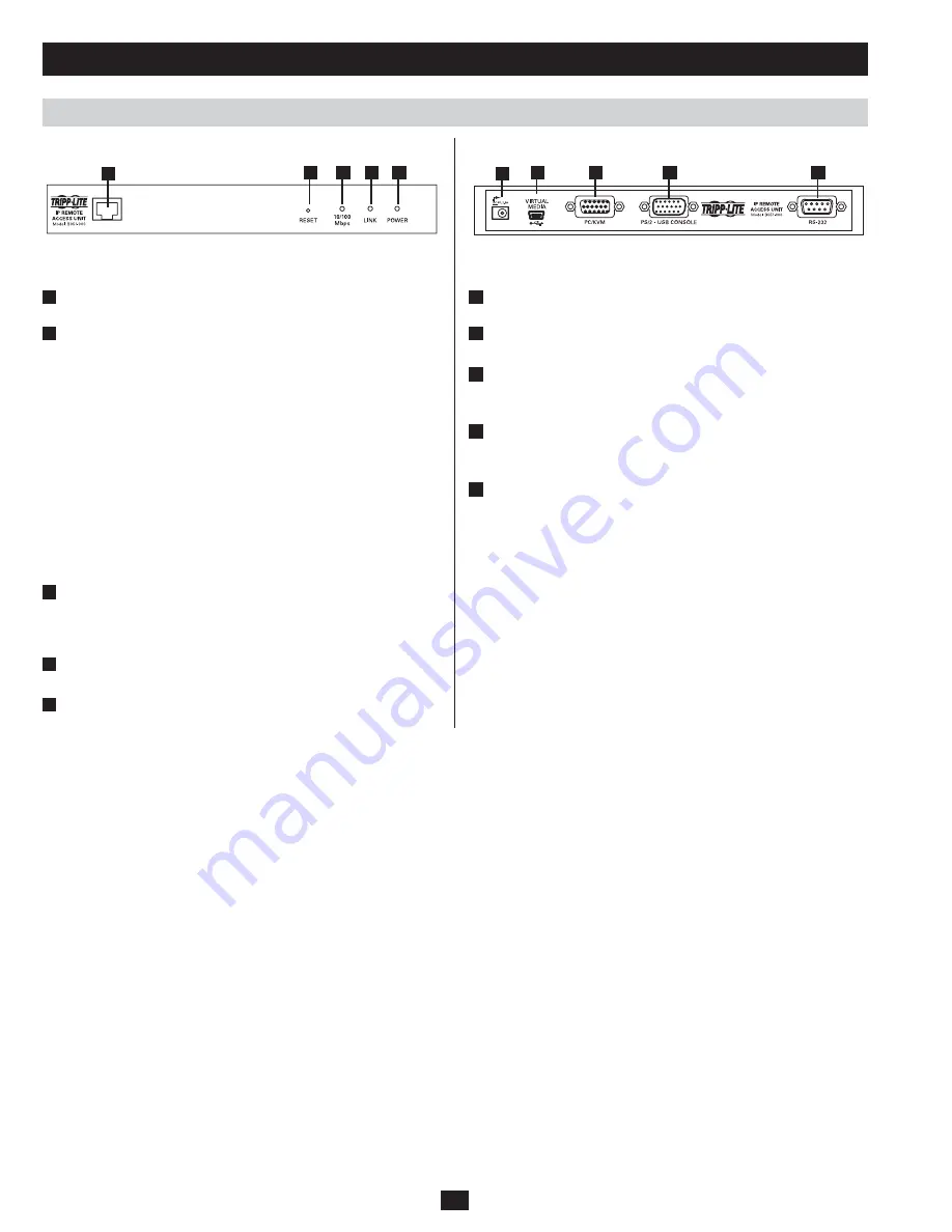
Front View
Rear View
No . Component
Description
1
LAN Port
The Cat5e/6 cable that connects the B051-000
to a network plugs in here.
2
Reset Switch
Pressing and releasing this switch will
1.
perform a system reset.
Pressing and holding the switch for more
2.
than 3 seconds restores the B051-000 to its
factory default configuration settings.
Pressing and holding this switch while
3.
powering the unit on will restore the factory
default firmware version. This operation
should only be performed in the event of a
firmware upgrade failure that results in the
device becoming inoperable.
Note: This switch is recessed and must be
pushed with a thin object, such as the end of a
paper clip or ballpoint pen.
3
10/100 Mbps
LED
This LED lights Orange to indicate a data
transmission speed of 10Mbps, or Green to
indicate a Data transmission speed of 100
Mbps.
4
Link LED
This LED flashes Green to indicate that the
B051-000 is being accessed remotely.
5
Power LED
This LED lights Orange when the B051-000 is
powered-on and ready to operate.
No . Component
Description
1
Power Jack
The included power adapter connects to the unit
here.
2
Virtual Media
Port
The included USB 2.0 device cable connects
here when using the Virtual Media feature.
3
PC/KVM Port
The KVM cable kit that connects the B051-000
to a KVM switch or server connects to the unit
here.
4
Console port
The console connector kit that connects a Local
Console to the B051-000 connects to the unit
here.
5
RS-232 port
An RS-232 serial port is provided for out-of-
band and low bandwidth modem and serial
terminal connections.
1
1
2
2
3
3
4
4
5
5


