


PDx-170-57-E / TMCM-170 Hardware Manual (V1.10 / 2011-NOV-24)
7
Copyright © 2011, TRINAMIC Motion Control GmbH & Co. KG
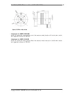
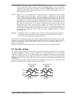
I/O board
(top view)
1
2
3
4
5
Int
er
fac
e
1
2
3
4
5
6
7
8
I/O
1
2
3
4
5
Hall
sensors
1
2
3
4
5
E
nc
od
er
Driver board
(top view)
Motor
U V W
Power
+
Interface
Enc
I/O
Hall
Motor
Power
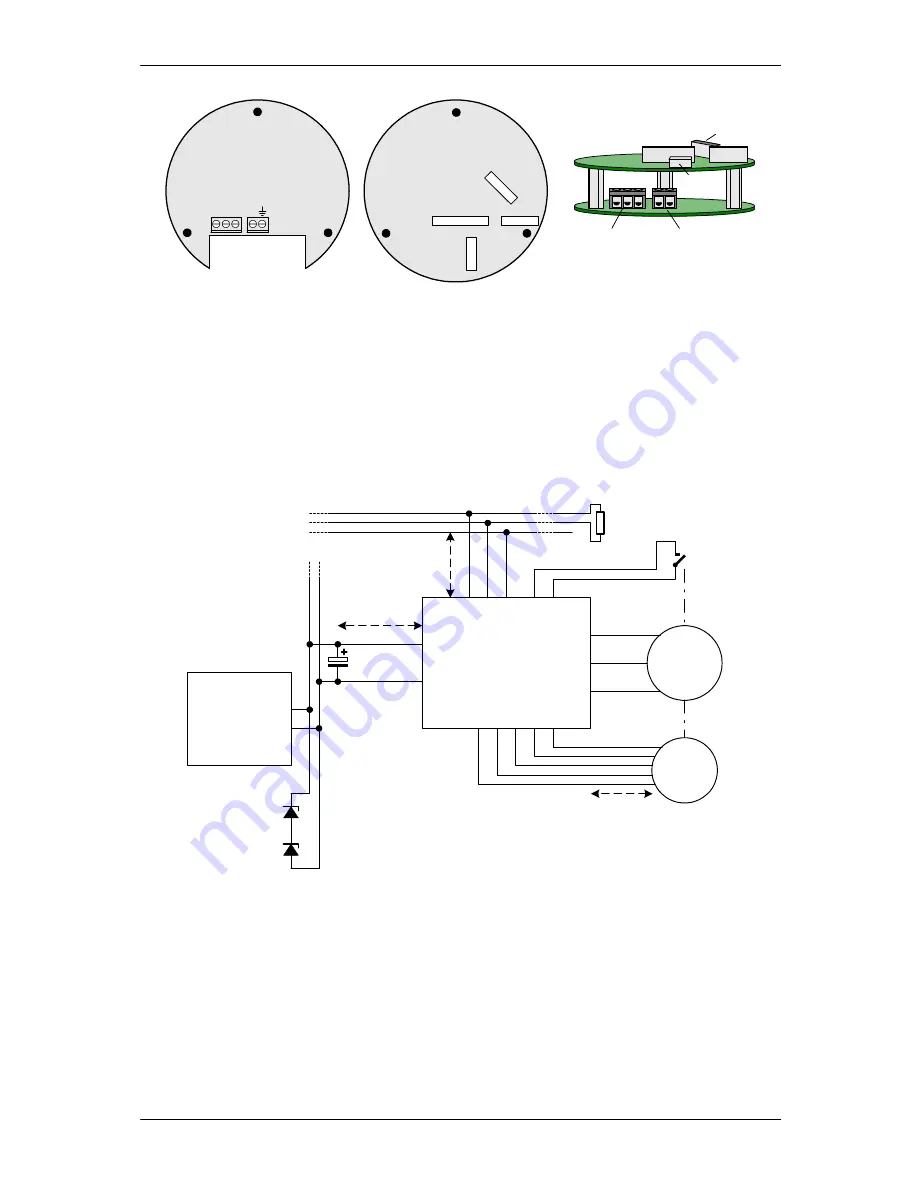
Important note:
For the PANdrives
™
PD-170, the motor coils, hall sensor signals and encoder signals
are already connected. Nevertheless, in order to connect power supply the upper interface board has
to be removed. Never connect or disconnect the boards while power is switched on!
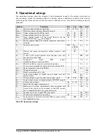
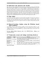
4.2
Application circuit
The schematic shows a typical application circuit using CAN bus interface. Optionally the unit allows
connection of motor hall sensors and encoder N-channel as well as further digital / analog pins and
different interface options.
TMCM-170
R
e
fe
re
n
c
e
S
w
.
BLDC-
Motor
Encoder
Mech. Axis
GN
D
/S
TOP
GN
D
I/O
Interface
C
A
N
L
C
A
N
H
System's
CAN bus
keep distance
short for CAN
110R
Termination
resistor at bus end
U
V
W
GN
D
Encoder
+5
V
CHA
CHB
VS
GND
Place unit near
encoder / motor
4700µ,
63V
48V system
power
supply
optional overvoltage
suppressor:
high power zener /
zener transistor
circuit
+
-
optional
capacitor if > 2m
CHN
Figure 4.2: Application circuit


