


PDx-170-57-E / TMCM-170 Hardware Manual (V1.10 / 2011-NOV-24)
11
Copyright © 2011, TRINAMIC Motion Control GmbH & Co. KG
5
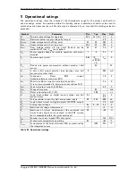
Operational ratings
The operational ratings show the intended / the characteristic range for the values and should be
used as design values. An operation within the limiting values is possible, but shall not be used for
extended periods, because the unit life time may be shortened. In no case shall the limiting values be
exceeded.
Symbol
Parameter
Min
Typ
Max
Unit
V
S
Power supply voltage for operation
12.5
14 - 48
52
V
V
SMAX
Maximum power supply voltage (for surge)
60
V
V
SLOOFF
Under voltage switch off trip point
9.5
10
10.5
V
V
SON
Under voltage switch on trip point
10.5
12
12.5
V
V
SOFF
Over voltage switch off trip point (Feature can be
switched off, then V
SMAX
limit applies)
52
55
58
V
V
SD
Power supply voltage for module operation with motor
disabled
7
8
9.5
V
I
S
Power supply current
0.04
(P
Motor
+3..10W)
/ V
S
I
MOT
A
P
ID
Module idle power consumption without encoder / hall
sensor
2.4
W
V
5
5 Volt (+-4%) output external load (encoder plus hall
sensors plus other load)
0
200
mA
I
MC
Continuous
Motor
RMS
current
(module surface at maximum 85°C)
10
A
I
MP
Short time Motor current in acceleration periods
It is not recommended to set motor current above 12A!
14
A
I
MPP
Peak coil output current for 100ms
40
A
f
CHOP
Chopper frequency
20
kHz
T
SL
Motor output slope (U, V, W)
100
ns
V
I
Logic input voltage on digital inputs, encoder and hall
sensor inputs
-0.3
V
CC
+
0.3
V
I
I
Pull-up resistor current for hall and encoder inputs
50
250
400
µA
V
O
Logic output current on digital outputs (5V CMOS output)
10
mA
V
IA
Analog input voltage
-24
0 – 10
24
V
E
V
Exactness of voltage measurement
-5
+5
%
E
C
Exactness of current measurement (the measured coil
current value might not correspond to the RMS current,
but is repeatable within the given exactness)
-10
+10
%
f
ENC
Encoder count rate (signals 50% duty cycle)
13.3
MHz
T
O
Environment temperature operating
-25
+85
°C
T
board
Temperature of the bottom (driver) PCB, as measured by
the integrated sensor.
<105
115
°C
Table 5.1: Operational ratings


