Trinamic PD4-170-57-E Скачать руководство пользователя страница 14

PDx-170-57-E / TMCM-170 Hardware Manual (V1.10 / 2011-NOV-24) 

  14 

Copyright © 2011, TRINAMIC Motion Control GmbH & Co. KG 


“Actual  Commutation  Offset”  gives  the  angular  relationship  between  motor  and  encoder. 
Therefore  this  parameter  has  to  be  stored  correctly  in  EEPROM  before  power  on!  Do  not 
enable this mode, before the parameter has been set correctly. Mode 4 helps for the very 
first initialization of this mode. 


Mode 4

  helps  to  do  a  first  initialization  and  tuning  of  mode  3.  It  searches  for  the  N-channel 

reference point first, and then does a 

mode 2

 initialization to determine the correct setting 

for the “Actual Commutation Offset”. The encoder N-channel polarity has to be high active 
for this mode (the actual setting of the encoder null polarity has no influence in this mode), 
and, additionally, you have to specify the polarity of the encoder A- and B-channel upon N-
channel activity using the setting “Encoder Null Polarity”, bits 1 and 2. The correct setting of 
this  depends  on  the  encoder.  If  the  N-channel  referencing  fails,  the  motor  does  two  full 
rotations  and  then  stops.  Try  again  with  reversing  the  “Encoder  Null  Polarity”.  After 
successfully initializing the “Actual Commutation Offset”, you can try moving the motor and 
tune the offset, if desired. Then store the offset and switch to 

mode 3

. If any encoder errors 

are  flagged  during  operation  of  the  motor,  retry  with  a  modified  setting  for  A-  and  B-
channel polarity. 


Attention:   Initialization modes 1 to 4 apply a high current to the motor for a few seconds. Be sure 

to parameterize the initialization current correctly (i.e. not more than 2* the maximum 
rated motor current) before first powering on the unit. 

 
The quality of the initialization phase result can be checked by rotating the motor left and right at the 
maximum velocity (use a velocity setting slightly higher than the motor can follow). Maximum velocity 
for left and right direction shall not differ by more than a few percent. Also make some checks if 
results are reproducible.  
Whenever changing one of these parameters, re-power the unit to restart initialization phase! 
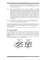
 

6.3


Encoder setting 

The N-channel (index channel) of the encoder is not required for motor operation, but it is very good 
for  motor  initialization,  because  it  gives  an  absolute  and  exact  reference  point.  So,  the  motor 
initialization  modes  3  and  4  use  the  N-channel  for  motor  initialization.  Behavior  of  the  N-channel 
signal is very dependent on the encoder type and has to be taken into account for the setting of the 
TMCM170 encoder interface. Please refer to the following figure for correct setting of the Encoder Null 
Polarity flag.  
A wrong setting may either hinder the module from initializing the sine mode, or might lead to the 
Encoder Error flag being set, in spite of correct encoder function. 
 

zero event

Enc-A

Enc-B

Enc-N

(index)

Set Encoder Null

Polarity to

binary 011

Set Encoder Null

Polarity to

binary 001

zero event

CW turn

CCW turn

CW turn

CCW turn

0

1

0

0


Содержание PD4-170-57-E

Страница 1: ...mburg Germany www trinamic com V 1 10 HARDWARE MANUAL TMCM 170 57 controller driver module up to 10A RMS 12 48V DC CAN RS232 RS485 optional PDx 170 57 E mechatronic device with 57 mm BLDC servo motor...

Страница 2: ...ements 12 5 2 Bus interface 12 5 2 1 Terminating the RS485 network 12 6 Functional description 13 6 1 Setting the basic values for operation using the demonstration application 13 6 2 Start up for enc...

Страница 3: ...equipment intended to support or sustain life and whose failure to perform when properly used in accordance with instructions provided can be reasonably expected to result in personal injury or death...

Страница 4: ...stability drives Extremely compact decentralized motor electronics Motor Encoder type Sine or block commutated BLDC motors with encoder and with without additional hall sensors Hall sensor based motor...

Страница 5: ...uired Order code Description Dimensions mm PD4 170 57 E option PANdrive 0 32Nm 132 x 61 x 61 without motor axis PD5 170 57 E option PANdrive 0 42Nm 152 x 61 x 61 without motor axis TMCM 170 option BLD...

Страница 6: ...perature pre warning threshold is exceeded high when module shut down due to overtemperature CUR LED 5V TTL output High when module goes into current limiting mode or into overvoltage switch off Toggl...

Страница 7: ...ect or disconnect the boards while power is switched on 4 2 Application circuit The schematic shows a typical application circuit using CAN bus interface Optionally the unit allows connection of motor...

Страница 8: ...height 28mm 16mm highest part mounting holes diameter is 2 8mm Figure 4 3 Dimensions of TMCM 170 and PD 170 32 00 25 97 14 50 27 00 13 50 27 00 27 00 30 50 46 77 61 00 Top view of Driver board All val...

Страница 9: ...sulation Class B Radial Play 0 02 mm 450G load Max Radial Force 75N 10mm from flange Max Axial Force 15N Dielectric Strength 500 VDC For One Minute Insulation Resistance 100M Ohm min 500VDC Recommende...

Страница 10: ...Switch the reverse hall sensor polarity on and the reverse encoder direction off Use the basic control and diagnostics software or TMCL IDE Adjustments for QBL5704 94 04 032 Switch the reverse hall s...

Страница 11: ...PID Module idle power consumption without encoder hall sensor 2 4 W V5 5 Volt 4 output external load encoder plus hall sensors plus other load 0 200 mA IMC Continuous Motor RMS current module surface...

Страница 12: ...because it saves energy precautions have to be taken to limit the supply voltage to within the operational limits The TMCM 170 contains an overvoltage protection circuit which disables braking whenev...

Страница 13: ...nce Thus the unit needs an internal start up procedure which determines the encoder position with respect to the actual pole motor orientation The TMCM 170 provides basically two modes for encoder ini...

Страница 14: ...d setting for A and B channel polarity Attention Initialization modes 1 to 4 apply a high current to the motor for a few seconds Be sure to parameterize the initialization current correctly i e not mo...

Страница 15: ...er be done via a central unit operating the motor via its bus interface or a reference switch can be connected to the stop input pull down to 0V at reference point The position counter can be automati...

Страница 16: ...sure about this If the short time motor coil current is not limited to a maximum of about 40A this could destroy the unit There are a number of aspects when using the current limiting function The cur...

Страница 17: ...ion V0 90 or later for connector pinning 0 92 First release Added encoder N channel initialization 0 93 Added encoder N channel for automatic correction and encoder error flag 0 94 Allows specifying o...

Страница 18: ...B SGP 253 0 4 Motor Pole 4 SGP 254 0 0 Hall Sensor Invert PD4 SGP 254 0 1 Hall Sensor Invert PD5 SGP 250 0 2000 Encoder Steps per Rotation SGP 252 0 1 Reverse Encoder Null Polarity SGP 251 0 1 Revers...

Отзывы: