Trinamic PD4-170-57-E Скачать руководство пользователя страница 12

PDx-170-57-E / TMCM-170 Hardware Manual (V1.10 / 2011-NOV-24) 

  12 

Copyright © 2011, TRINAMIC Motion Control GmbH & Co. KG 


5.1


Power supply requirements 

The  power  supply  should  be  designed  in  a  way,  that  it  supplies  the  nominal  motor  voltage  at  the 
desired maximum motor power. In no case shall the supply value exceed the upper / lower voltage 
limit. The BLDC motor unit uses a chopper principle, i.e. the power supply to the motor is pulsed at a 
frequency of 20kHz. To ensure reliable operation of the unit, the power supply has to have a sufficient 
output capacitor and the supply cables should have a low resistance, so that the chopper operation 
does not lead to an increased power supply ripple directly at the unit. Power supply ripple due to the 
chopper operation should be kept at a maximum of a few 100mV.  
 

Therefore we recommend to 

˗ 

keep power supply cables as short as possible 

˗ 

use large diameter for power supply cables 

˗ 

if  the  distance  to  the  power  supply  is  large  (i.e.  more  than  2-3m),  use  a  robust  4700µF  or 
larger additional filtering capacitor located near to the motor driver unit. 

 
An effect the power supply has to cope with, is, that the motor can feed back substantial current into 
the power supply whenever it is actively braked! While this generally is a positive effect (because it 
saves  energy),  precautions  have  to  be  taken,  to  limit  the  supply  voltage  to  within  the  operational 
limits. The TMCM-170 contains an overvoltage protection circuit, which disables braking whenever the 
upper supply voltage limit is exceeded. This automatic function may lead to an unwanted behavior, 
i.e. overshooting the target position, and thus can  be disabled. Disabling the overvoltage protection 
should only be done, provided that the user takes additional precautions to limit the voltage: 
 

It is recommended to use  

a)


a large capacitor on the power supply lines able to store substantial part of feed back energy 

b)


a zener / suppressor diode circuitry, limiting the power supply voltage to a maximum of 52-
60V 


5.2


Bus interface 

The TMCM-170 supports an optional CAN interface. It can be operated via CAN or RS232 / RS485 in the 
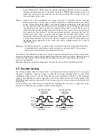
same  way. CAN  bus and RS485 require a  termination resistor at both ends  of the cable (but not at 
every unit). This resistor is integrated and can be activated on the TMCM-170 by shorting a soldering 
bridge  (dotted  line  in  the  connector  drawing),  but  for  most  purposes  it  is  more  elegant  to  provide 
this resistor external to the unit.  

5.2.1


Terminating the RS485 network 

For RS485 in addition to the termination resistor a termination network is required, which forces an 
“inactive” level to the line, when no driver is on. Typically, use a 1K resistor  to + 5V for RS485+ line 
and a 1K resistor to GND for the RS485- line at some point of the network. 
 

Содержание PD4-170-57-E

Страница 1: ...mburg Germany www trinamic com V 1 10 HARDWARE MANUAL TMCM 170 57 controller driver module up to 10A RMS 12 48V DC CAN RS232 RS485 optional PDx 170 57 E mechatronic device with 57 mm BLDC servo motor...

Страница 2: ...ements 12 5 2 Bus interface 12 5 2 1 Terminating the RS485 network 12 6 Functional description 13 6 1 Setting the basic values for operation using the demonstration application 13 6 2 Start up for enc...

Страница 3: ...equipment intended to support or sustain life and whose failure to perform when properly used in accordance with instructions provided can be reasonably expected to result in personal injury or death...

Страница 4: ...stability drives Extremely compact decentralized motor electronics Motor Encoder type Sine or block commutated BLDC motors with encoder and with without additional hall sensors Hall sensor based motor...

Страница 5: ...uired Order code Description Dimensions mm PD4 170 57 E option PANdrive 0 32Nm 132 x 61 x 61 without motor axis PD5 170 57 E option PANdrive 0 42Nm 152 x 61 x 61 without motor axis TMCM 170 option BLD...

Страница 6: ...perature pre warning threshold is exceeded high when module shut down due to overtemperature CUR LED 5V TTL output High when module goes into current limiting mode or into overvoltage switch off Toggl...

Страница 7: ...ect or disconnect the boards while power is switched on 4 2 Application circuit The schematic shows a typical application circuit using CAN bus interface Optionally the unit allows connection of motor...

Страница 8: ...height 28mm 16mm highest part mounting holes diameter is 2 8mm Figure 4 3 Dimensions of TMCM 170 and PD 170 32 00 25 97 14 50 27 00 13 50 27 00 27 00 30 50 46 77 61 00 Top view of Driver board All val...

Страница 9: ...sulation Class B Radial Play 0 02 mm 450G load Max Radial Force 75N 10mm from flange Max Axial Force 15N Dielectric Strength 500 VDC For One Minute Insulation Resistance 100M Ohm min 500VDC Recommende...

Страница 10: ...Switch the reverse hall sensor polarity on and the reverse encoder direction off Use the basic control and diagnostics software or TMCL IDE Adjustments for QBL5704 94 04 032 Switch the reverse hall s...

Страница 11: ...PID Module idle power consumption without encoder hall sensor 2 4 W V5 5 Volt 4 output external load encoder plus hall sensors plus other load 0 200 mA IMC Continuous Motor RMS current module surface...

Страница 12: ...because it saves energy precautions have to be taken to limit the supply voltage to within the operational limits The TMCM 170 contains an overvoltage protection circuit which disables braking whenev...

Страница 13: ...nce Thus the unit needs an internal start up procedure which determines the encoder position with respect to the actual pole motor orientation The TMCM 170 provides basically two modes for encoder ini...

Страница 14: ...d setting for A and B channel polarity Attention Initialization modes 1 to 4 apply a high current to the motor for a few seconds Be sure to parameterize the initialization current correctly i e not mo...

Страница 15: ...er be done via a central unit operating the motor via its bus interface or a reference switch can be connected to the stop input pull down to 0V at reference point The position counter can be automati...

Страница 16: ...sure about this If the short time motor coil current is not limited to a maximum of about 40A this could destroy the unit There are a number of aspects when using the current limiting function The cur...

Страница 17: ...ion V0 90 or later for connector pinning 0 92 First release Added encoder N channel initialization 0 93 Added encoder N channel for automatic correction and encoder error flag 0 94 Allows specifying o...

Страница 18: ...B SGP 253 0 4 Motor Pole 4 SGP 254 0 0 Hall Sensor Invert PD4 SGP 254 0 1 Hall Sensor Invert PD5 SGP 250 0 2000 Encoder Steps per Rotation SGP 252 0 1 Reverse Encoder Null Polarity SGP 251 0 1 Revers...

Отзывы: