


Monopack 2 Manual V1.04
8
Copyright © 2010, TRINAMIC Motion Control GmbH & Co. KG
2.7
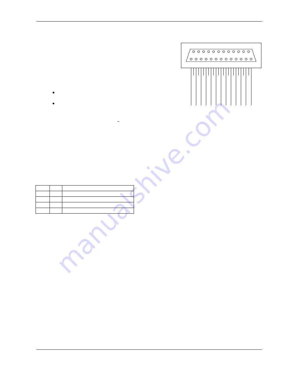
The 25 pin Sub-D Socket
This socket contains the RS485 interface, the CAN interface, the
STEP/DIRECTION interface and the alarm input and output. The signals
of the incremental encoder input and the stop switch inputs are
output
here as differential signals. The following subsections describe those
interfaces.
2.7.1
CAN and RS485 Interface
For the CAN and the RS485 interface, the same pins are used. So the
interface which shall be used must be selected via the DIP switches:
To use the CAN interface, set switch 1 and 2 to ON and
switch 3 and 4 to OFF position.
To use the RS485 interface, set switch 1 and 2 to OFF and
switch 3 and 4 to ON position.
The termination of both interfaces (120 Ohms) can be switched on and
off with switch 6. Switch 5 is not used.
Attention
: Changing between
RS485 and CAN interface requires a hardware reset (by powering off for
a short time).
2.7.2
The Step/Direction Interface
The Step/Direction interface uses differential signals. After powering on, the Monopack is in Step/Direction mode
so that the Step/Direction interface is usable. After getting the first RS485 or CAN command the Monopack leaves
the Step/Direction mode and enters the command mode where the Step/Direction interface can not be used. It is
possible to switch back to Step/Direction mode by a command.
The motor current control inputs MC0 and MC1 also belong to the Step/Direction interface. Using these inputs, the
motor current can be controlled by hardware in three steps (please see also section 4.2.1):
MC0 MC1 Motor current
0
0
1/3 of configured maximum current
1
0
2/3 of configured maximum current
0
1
2/3 of configured maximum current
1
1
Configured maximum current
In contrast to the old Monopack, these motor current settings can also be controlled by software (please see
section 4.2.1). The step and direction inputs are also provided on the Step/Direction input socket. These are
internally connected to the step/direction inputs of the 25-pin socket.
2.7.3
The Alarm Input
The alarm input is a differential input which can be used to stop the motor in case of emergency. To connect a
key to this input, simply connect it between and +5V (from the incremental encoder connector) and
connect the AlarmIN- input to ground.
2.7.4
The Alarm Output
This differential output is set high in case of an alarm or error condition. Alarm and error conditions can be
cleared by command $74 (s. 4.6.2).
2.7.5
The Incremental Encoder Output
The incremental encoder outputs (EnchA+/-, EnchB+/-, EnchN+/-) provide the encoder signals from the encoder input
(s. 2.4) converted to differential signals.
2.7.6
The Stop Switch Outputs
The stop switch outputs (StopL+/- and StopR+/-) provide the signals from the stop switch inputs (s. 2.3) converted
to differential signals.
1
13
14
25
CA
NL/RS
48
5-
C
A
N
H
/R
S
4
8
5
+
E
nCHB
-
E
n
C
H
B
+
S
top
L-
S
to
p
L
+
A
larmIN-
A
MC1-
M
C
1
+
DIR-
D
IR
+
G
ND
E
nCHN-
E
n
C
H
N
+
E
nCHA
-
E
n
C
H
A
+
S
top
R-
S
to
p
R
+
A
larmO
UT
-
A
larmO
UT
+
MC0-
M
C
0
+
S
T
E
P
-
S
T
E
P
+