cascade Settings
34
Boiler Enabling algorithm
The Master boiler uses the following algorithm to determine when the next
boiler can be enabled:
Once the currently fired boilers reach the calculated firing rate, the next
boiler can be enabled without affecting the overall cascade firing rate. For
example, the calculation for a Cascade System consisting of two PRES-
TIGE Solo 399s would be:
Once the first PRESTIGE Solo 399 firing rate reaches 60%, the second
PRESTIGE Solo 399 can be enabled. Both will then fire at the minimum
30% firing rate so that the overall output from the Cascade System remains
the same.
Boiler disabling algorithm
Once the firing rate of all currently fired boilers decreases to the Minimum
Firing Rate, a boiler can be disabled. The boilers which continue to fire
will increase their firing rate if required to replace the output of the dis-
abled boiler.
Stable cascade operation requires that all boilers in a cascade System
be the same size. Mixing boiler sizes in a cascade System could lead
to temperature fluctuations and erratic cascade operation.
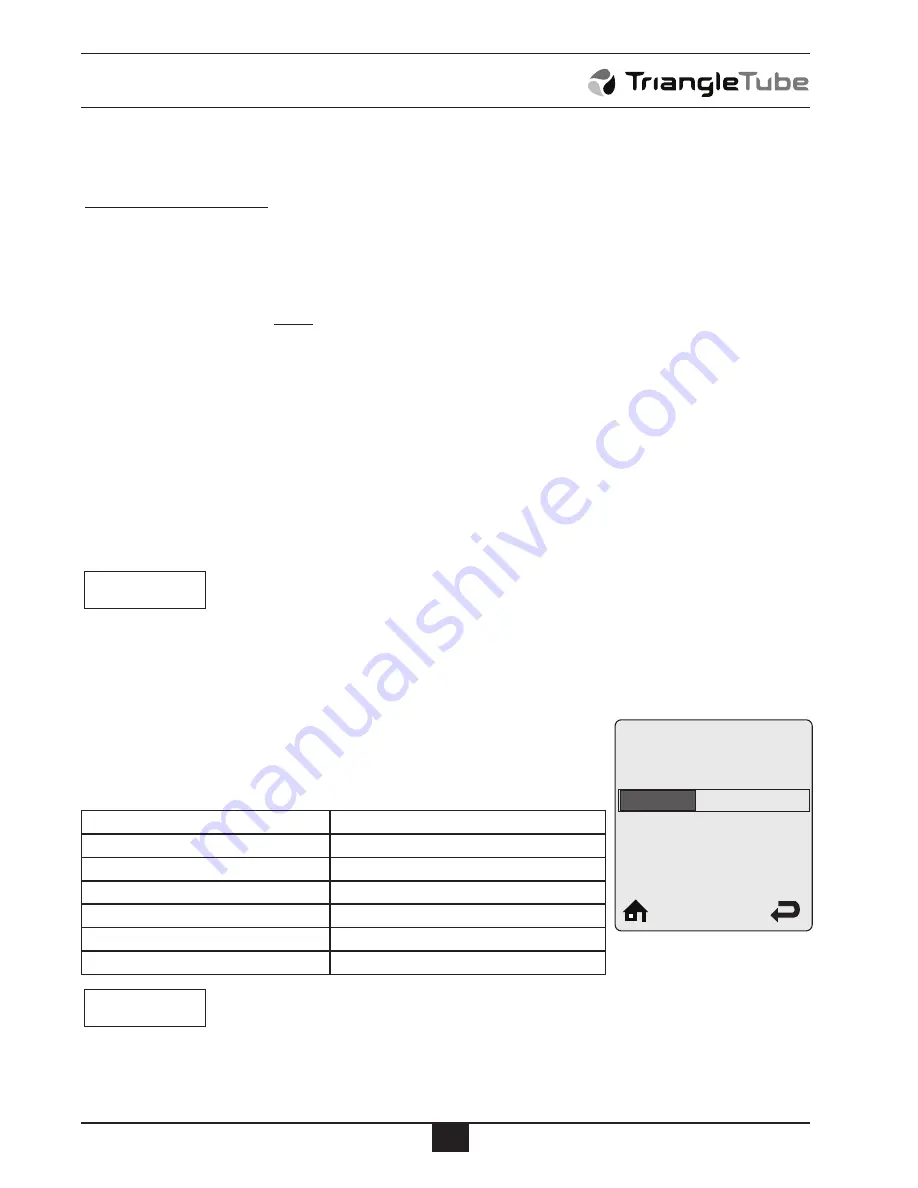
Maximum firing Rate
default: 398 MBH
Maximum Firing Rate is the maximum firing rate of a single boiler in the
Cascade System. Press the
LEfT
or
RIGHT
buttons to adjust the
Maximum Firing Rate then press the
oK
button to store the setting. The
recommended settings are:
Stable cascade operation requires that all boilers in a cascade System be
the same size. Mixing boiler sizes in a cascade System could lead to tem-
perature fluctuations and erratic cascade operation.
NOTICE
NOTICE
Prestige Model
Maximum Firing Rate
Solo 60
57 MBH
Solo 110 Natural Gas
109 MBH
Solo 110 Propane Gas
95 MBH
Solo 175
170 MBH
Solo 250
245 MBH
Solo 399
398 MBH
0MBH
869MBH
398 MBH
Maximum
Firing Rate
Number of Boilers 1
Number of Boilers Firing
x Minimum Firing Rate = Individual Boiler Firing Rate
1 + 1
1
x 30% = 60%
Содержание Prestige Excellence
Страница 13: ...11 cH Settings fig 2 System Piping with System Pump cH1 cH2 dHW...
Страница 14: ...12 cH Settings fig 3 System Piping with System Pump cH1 cH2...
Страница 15: ...13 fig 4 System Piping with System Pump cH2 cH Settings...
Страница 33: ...31 cascade Installation fig 11 Split cascade Wiring note Reference Fig 10 page 30 for cascade piping...


