


TE0790 TRM
Revision: v.37
Copyright © 2019 Trenz Electronic GmbH
16 of 27
http://www.trenz-electronic.de
6
http://www.ftdichip.com/Support/Documents/DataSheets/ICs/DS_FT2232H.pdf
7
http://www.ftdichip.com
8
https://wiki.trenz-electronic.de/display/PD/CPLD+Firmware
6 On-board Peripherals
6.1 FTDI FT2232H IC
The FTDI FT2232H chip provides a variety of industry standard serial or parallel interfaces. On the TE0790 adapter
board at current available SC CPLD firmware the functions USB2.0 to JTAG, UART and user GPIO's.
By programing the firmware of the SC CPLD and special EEPROM configurations further further functionalities are
available of the FTDI chip which converts signals from USB2.0 to a variety of standard serial and parallel interfaces.
Refer to the FTDI
to get information about the capacity of the FT2232H IC.
6.2 Configuration EEPROM
The external EEPROM can be used to customize the TE0790 adapter board by setting numerous parameters of the
FT2232H IC, enabling different functionalities and configuring serial or parallel interfaces.
The EEPROM is programmable in-circuit over USB using a utility program called FT_PROG available from
FTDI’s
web site (
6.3 System Controller CPLD
The System Controller CPLD (U1) is provided by Lattice Semiconductor LCMXO2-256HC (MachXO2 Product Family).
The SC-CPLD is the central system management unit where essential control signals are logically linked by the
implemented logic in CPLD firmware, which generates output signals to control the system, the on-board
peripherals and the interfaces.
Signals of the serial or parallel interfaces are by-passed, forwarded and controlled by the System Controller CPLD.
The internal routing of the signals on the System Controller CPLD between the USB2.0 interface and pin header J2
depends on its configured firmware. CPLD can be set into JTAG chain
via
. Refer to
the
for more information about the currently available System Controller CPLD firmware
and for download.
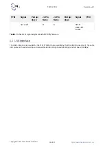
6.4 DIP-switch
The DIP-switch S2 is to set different modes of powering the on-board components, the I/O voltages and to enable
programming the adapter board CPLD by JTAG interface:
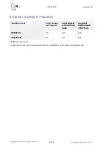
Important notice on TE0790-xx variants:
Do not access the FT2232H EEPROM using FTDI programming tools, doing so will erase normally invisible
user EEPROM content and invalidate stored Xilinx JTAG license. Without this license the on-board JTAG
will not be accessible any more with any Xilinx tools. Software tools from FTDI website do not warn or ask
for confirmation before erasing user EEPROM content.