background image

9

Pub. No. 22-1840-14

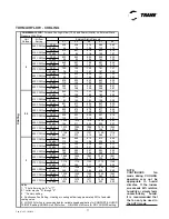
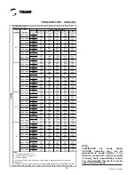
TUHM AIRFLOW - HEATING

0.1

0.3

0.5

0.7

0.9

CFM

592

617

623

617

606

Temp. Rise

61

59

58

59

60

Watts

78

109

141

173

233

CFM

626

651

655

649

639

Temp. Rise

58

56

55

56

57

Watts

79

110

142

175

236

CFM

660

684

688

682

671

Temp. Rise

55

53

53

53

54

Watts

81

111

144

177

241

CFM

732

755

757

751

739

Temp. Rise

50

48

48

48

49

Watts

87

115

149

185

254

CFM

1048

1065

1060

1052

1038

Temp. Rise

60

59

59

60

61

Watts

149

169

208

252

358

CFM

1107

1123

1116

1108

1094

Temp. Rise

57

56

56

57

58

Watts

167

186

226

271

386

CFM

1165

1181

1173

1165

1150

Temp. Rise

54

53

54

54

55

Watts

187

204

245

292

417

CFM

1291

1304

1293

1284

1269

Temp. Rise

49

48

49

49

50

Watts

236

250

293

343

490

CFM

1466

1476

1461

1451

1435

Temp. Rise

60

59

60

60

61

Watts

319

330

374

430

613

CFM

1548

1556

1540

1529

1512

Temp. Rise

57

56

57

57

58

Watts

364

373

419

476

679

CFM

1629

1637

1618

1608

1590

Temp. Rise

54

54

54

54

55

Watts

413

419

467

527

750

CFM

1803

1807

1785

1774

1755

Temp. Rise

49

48

49

49

50

Watts

529

532

582

646

864

100% 

(high) 

Heat

Low

1460

Medium Low

1540

Medium**

1620

High

1790

High

1289

672

High

743

639

Medium**

Low

1051

Medium Low

1109

606

Medium**

1166

40% 

(low) 

Heat

Low

H

eat

ing

*UHMC100ACV4VB^ 

Furnace Heating Airflow (CFM) and Power (Watts) vs. External Static Pressure With Filter

Airflow 

Setting

Target Airflow

(See Note 5)

External Static Pressure

Medium Low

65% 

(medium) 

Heat

0.1

0.3

0.5

0.7

0.9

CFM

728

758

785

805

819

Temp. Rise

62

59

57

56

55

Watts

119

107

102

94

108

CFM

769

797

822

840

853

Temp. Rise

58

56

54

53

53

Watts

113

107

111

113

133

CFM

813

841

864

880

890

Temp. Rise

55

53

52

51

50

Watts

108

107

122

135

160

CFM

863

889

910

923

930

Temp. Rise

52

50

49

49

48

Watts

104

108

135

160

191

CFM

1213

1232

1237

1232

1220

Temp. Rise

60

60

59

60

60

Watts

131

160

253

345

405

CFM

1279

1297

1299

1290

1274

Temp. Rise

57

57

56

57

58

Watts

147

178

281

382

445

CFM

1353

1369

1367

1355

1335

Temp. Rise

54

54

54

54

55

Watts

168

201

313

423

489

CFM

1434

1448

1443

1426

1402

Temp. Rise

51

51

51

51

52

Watts

197

229

352

469

538

CFM

1699

1707

1690

1659

1621

Temp. Rise

60

60

60

61

63

Watts

325

349

495

628

698

CFM

1790

1797

1775

1740

1696

Temp. Rise

57

57

57

59

60

Watts

382

400

551

685

752

CFM

1892

1896

1870

1830

1781

Temp. Rise

54

54

54

56

57

Watts

453

462

616

750

813

CFM

2004

2006

1975

1929

1873

Temp. Rise

51

51

52

53

54

Watts

540

538

694

822

880

100% 

(high) 

Heat

Low

1700

Medium Low

1790

Medium**

1890

High

2000

High

1440

832

High

880

788

Medium**

Low

1224

Medium Low

1289

748

Medium**

1361

45% 

(low) 

Heat

Low

H

eat

ing

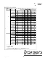
*UHMD120ACV5VB^ 

Furnace Heating Airflow (CFM) and Power (Watts) vs. External Static Pressure With Filter

Airflow 

Setting

Target Airflow

(See Note 5)

External Static Pressure

Medium Low

65% 

(medium) 

Heat

Notes:
1.  * First letter may be "A" or "T".

3.  ** Factory setting.

2.  ^ Letter may be “A” through “Z”.

4.  Continuous Fan Setting:  Heating or cooling airflow is approximately 50% of selected 
cooling value.
5.  LOW 350 cfm/ton is recommended for variable speed application for COMFORT & HUMID
CLIMATE setting; NORMAL is 400 cfm/ton;  HIGH 450 cfm/ton is for DRY CLIMATE setting.

6. Target airflow is field selectable for high (100%) heat.  Target airflow for low and medium 
heat are percentages of high heat and are not field selectable.

Содержание TDHMB060BCV3VB

Страница 1: ...B TDHMD120BCV5VB Direct or Non Direct Vent with Variable Speed Blower Variable Speed Inducer PUB NO 22 1840 14 UPFLOW TUHM UPFLOW HORIZONTAL TDHM DOWNFLOW DOWNFLOW HORIZONTAL Communicating Upflow Hori...

Страница 2: ...wer vent blower to increase efficien cy and provide a positive discharge of gas fumes to the outside BURNERS Multiport Inshot burners will give years of quiet and efficient service All models can be c...

Страница 3: ...quipment 4 Optional Equipment 5 General Data 6 7 TUHMB060ACV3VB 6 TUHMB080ACV3VB 6 TUHMC100ACV4VB 6 TUHMD120ACV5VB 6 TDHMB060BCV3VB 7 TDHMB080ACV3VB 7 TDHMC100ACV4VB 7 TDHMD120BCV5VB 7 Performance Dat...

Страница 4: ...with Comfort RTM Variable speed induced draft blower Silicon Nitride hot surface igniter with adaptive heat up PVC Venting 1 or 2 pipe option Integrated solid state control with self diagnostics Furn...

Страница 5: ...00 Filter Rack Kit Left bottom return only for TUHMB060 080 C100 Left right bottom returns for TUHMD120 BAYRACK960 Filter Kit Horizontal Conversion TUHMB060 080 BAYFLTR203 Filter Kit Horizontal Conver...

Страница 6: ...Stage Hot Surface Igniter Multiport Inshot 3 115 1 60 8 8 15 1 2 H x W x D 41 3 4 x 19 1 2 x 30 1 2 158 146 TUHMC100ACV4VB Upflow Horizontal Left 40 000 38 400 100 000 96 000 35 65 96 0 DIRECT 10 x 1...

Страница 7: ...dundant Three Stage Hot Surface Igniter Multiport Inshot 6 115 1 60 13 5 15 1 2 H x W x D 41 3 4 x 26 1 2 x 30 1 2 206 196 TDHMC100ACV4VB Downflow Horizontal Right 40 000 38 400 100 000 96 000 35 65 9...

Страница 8: ...Watts 57 90 129 127 177 CFM 661 704 717 673 696 Temp Rise 54 51 50 53 51 Watts 71 106 148 146 207 CFM 772 809 819 774 789 Temp Rise 46 44 44 46 45 Watts 99 136 184 176 253 CFM 757 794 805 760 776 Tem...

Страница 9: ...58 56 54 53 53 Watts 113 107 111 113 133 CFM 813 841 864 880 890 Temp Rise 55 53 52 51 50 Watts 108 107 122 135 160 CFM 863 889 910 923 930 Temp Rise 52 50 49 49 48 Watts 104 108 135 160 191 CFM 1213...

Страница 10: ...182 232 284 333 CFM 972 1015 972 957 1036 Watts 160 213 262 312 374 CFM 1057 1078 1085 1085 1078 Watts 191 249 306 360 415 CFM 1115 1137 1142 1140 1139 Watts 214 275 333 388 447 CFM 832 885 894 901 89...

Страница 11: ...atts 170 224 274 322 372 CFM 1170 1181 1184 1180 1174 Watts 206 262 317 370 423 CFM 1268 1276 1270 1199 1224 Watts 254 314 372 430 484 CFM 1321 1321 1306 1295 1251 Watts 287 351 415 477 518 CFM 972 99...

Страница 12: ...1297 1304 1299 1290 1275 Watts 234 288 345 402 455 CFM 1404 1409 1402 1393 1377 Watts 281 340 400 462 520 CFM 1512 1514 1505 1495 1478 Watts 336 399 464 530 595 CFM 1583 1584 1574 1564 1546 Watts 377...

Страница 13: ...FM 1750 1757 1748 1727 1696 Watts 447 525 603 676 732 CFM 1852 1857 1845 1823 1790 Watts 522 604 682 749 804 CFM 2004 2006 1992 1967 1947 Watts 651 742 811 863 966 CFM 2157 2156 2140 2050 1947 Watts 8...

Страница 14: ...ting or cooling airflow is approximately 50 of selected cooling value 5 LOW 350 cfm ton is recommended for variable speed application for COMFORT HUMID CLIMATE setting NORMAL is 400 cfm ton HIGH 450 c...

Страница 15: ...flow is approximately 50 of selected cooling value 5 LOW 350 cfm ton is recommended for variable speed application for COMFORT HUMID CLIMATE setting NORMAL is 400 cfm ton HIGH 450 cfm ton is for DRY C...

Страница 16: ...6 287 337 CFM 1003 1000 990 975 950 Watts 183 222 274 326 375 CFM 1075 1073 1059 1041 1011 Watts 220 263 314 364 408 CFM 1123 1121 1104 1084 1052 Watts 248 294 341 389 427 CFM 877 875 872 861 845 Watt...

Страница 17: ...7 1129 1114 Watts 221 272 319 366 411 CFM 849 865 873 872 864 Watts 113 156 196 235 276 CFM 915 928 935 932 923 Watts 134 179 221 261 303 CFM 980 992 997 993 982 Watts 158 205 248 290 333 CFM 1045 105...

Страница 18: ...1274 1248 1218 1182 Watts 286 344 392 439 500 CFM 1397 1378 1349 1316 1277 Watts 346 401 446 489 548 CFM 1501 1481 1451 1415 1373 Watts 411 463 503 541 595 CFM 1571 1550 1518 1481 1437 Watts 457 507 5...

Страница 19: ...92 1683 1612 1628 1629 Watts 415 454 554 634 728 CFM 1704 1802 1731 1751 1753 Watts 507 548 667 761 877 CFM 1778 1882 1810 1833 1836 Watts 577 617 753 857 991 CFM 1452 1534 1463 1474 1473 Watts 318 35...

Страница 20: ...ove See note 6 below for exception The inlet pipe can be of a larger diameter but never smaller than the vent pipe 3 MAXIMUM PIPE LENGTHS MUST NOT BE EXCEEDED THE LENGTH SHOWN IS NOT A COMBINED TOTAL...

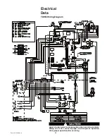
Страница 21: ...1840 14 Electrical Data TUHM Wiring Diagram CAUTION Label all wires prior to disconnection when servicing con trols Wiring errors can cause improper and dangerous opera tion Verify proper operation af...

Страница 22: ...840 14 Electrical Data TUHM Schematic Diagram CAUTION Label all wires prior to disconnection when servicing controls Wiring errors can cause improper and dangerous operation Verify proper operation af...

Страница 23: ...1840 14 Electrical Data TDHM Wiring Diagram CAUTION Label all wires prior to disconnection when servicing controls Wiring errors can cause improper and dangerous operation Verify proper operation aft...

Страница 24: ...840 14 TDHM Schematic Diagram Electrical Data CAUTION Label all wires prior to disconnection when servicing controls Wiring errors can cause improper and dangerous operation Verify proper operation af...

Страница 25: ...s furnace order BAYACCECOMM101 NOTE The BAYACCECOMM101 must be used when connecting an TFD whole house air cleaner to a furnace in communicating mode For 24 volt mode see the installation in the whole...

Страница 26: ...26 Pub No 22 1840 14 Communicating Indoor Unit with Communicating Comfort Control and 24VAC Single Stage Cooling 24 VAC Mode Indoor Unit with 24 VAC Comfort Control and 24VAC Single Stage Cooling...

Страница 27: ...27 Pub No 22 1840 14 24 VAC Mode Indoor Unit with 24 VAC Comfort Control and 24VAC 2 Stage or 2 Step Cooling 24 VAC Mode Indoor Unit with 24 VAC Comfort Control and 24VAC Single Stage Heat Pump...

Страница 28: ...K on the circuit board must be cut if an optional humidistat is installed HUMIDISTAT HOOKUP 24 V ONLY If an optional humidistat for humidity control in cooling is used the factory installed BK Jumper...

Страница 29: ...G NOTES 1 DIAMETER OF VENT PIPE MAY BE LIMITED TO 2 1 2 OR 3 ON SOME MODELS AT DIFFERENT ALTITUDES REFER TO THE VENT LENGTH TABLE FOR PROPER APPLICATION TUHM ACV Outline Drawing ALL DIMENSIONS ARE IN...

Страница 30: ...PLUG GAS CONNECTION ALTERNATE 1 5 8 HOLE WITH PLUG 20 1 4 1 3 4 X 2 13 32 CUTOUT HORIZONTAL DRAIN 1 5 8 HOLE WITH PLUG 1 1 2 x 2 1 2 OVAL GAS CONNECTION MODEL SEE NOTE 1 DIM A DIM B DIM C DIM D DHMB06...

Страница 31: ...31 Pub No 22 1840 14 Notes...

Страница 32: ...Trane has a policy of continuous product and product data improvement and reserves the right to change design and specifications without notice Trane 6200 Troup Highway Tyler TX 75707 www trane com...

Отзывы: