Installation Mechanical
28
RTAF-SVX001K-EN
Chilled Water Piping
Recommendations
Water Treatment
Dirt, scale, products of corrosion, and other foreign
material will adversely affect heat transfer between the
water and system components. Foreign matter in the
chilled-water system can also increase pressure drop and
consequently, reduce water flow. Proper water treatment
must be determined locally, depending on the type of
system and local water characteristics.
Units with Free-Cooling Option
Drainage
Locate the unit near a large capacity drain for water vessel
drain-down during shutdown or repair. Evaporators are
provided with drain connections. A vent on top of
evaporator waterbox prevents vacuum by allowing air
into evaporator for complete drainage.
Drain connections and vents are also provided on header
pipes for use when free-cooling option (model number
digit 42 = H) is selection.
All local and national codes apply.
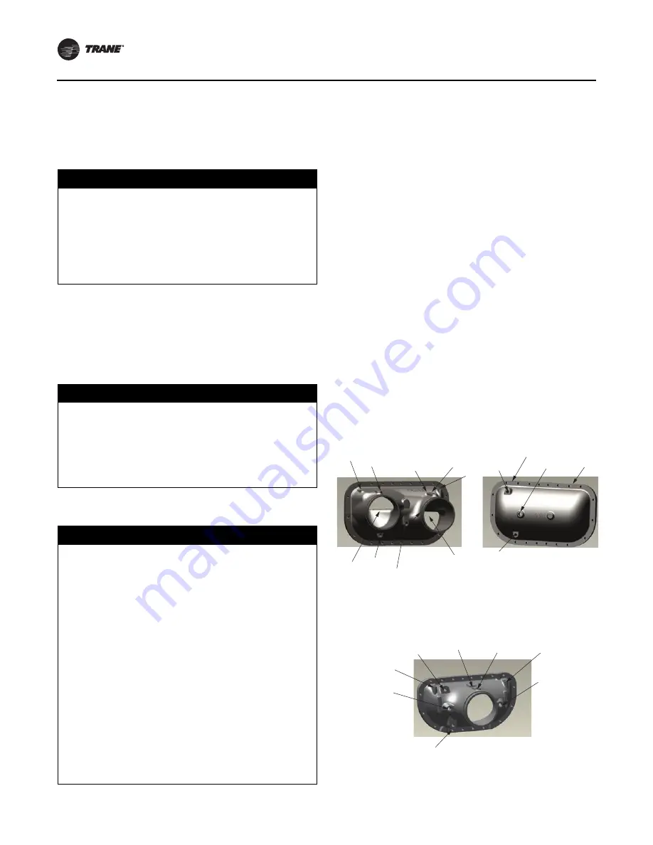
Evaporator Piping
Waterbox Configurations
Evaporator configuration varies with unit size. See figure
below for waterbox configurations and component
locations.
•
115 to 270 tons: 2-pass evaporator
•
280 to 520 tons: 1-pass evaporator
Note:
Flow sensor is installed in the inlet only. See
figure below.
NOTICE
Proper Water Treatment Required!
The use of untreated or improperly treated water could
result in scaling, erosion, corrosion, algae or slime. Use
the services of a qualified water treatment specialist to
determine what water treatment, if any, is required.
Trane assumes no responsibility for equipment failures
which result from untreated or improperly treated
water, or saline or brackish water.
NOTICE
Equipment Damage!
If using any commercial flushing/cleaning solution,
construct a temporary bypass around the unit to
prevent damage to internal components of the
evaporator/condenser. Trane assumes no responsibility
for equipment damage caused by flushing/cleaning
solutions or water-born debris.
NOTICE
Coil Damage!
Failure to follow instructions below could result in free-
cooling coil freeze.
For units with free-cooling option, introduction of
uninhibited water into the system is not recommended,
as it could lead to internal corrosion and risk of coil
freeze. To avoid free-cooling coil damage:
•
If the building loop needs to be charged with water
for testing purposes, isolate free-cooling coils by
closing free-cooling service shut-off valve and
modulating valve 6M4.
•
Completely drain any water inadvertently introduced
into the system, and replace with glycol fluid as
required for the free-cooling system.
•
If water was introduced for hydronic testing, and was
not immediately replaced with glycol solution, a
glycol (freeze inhibitor) solution must be introduced
to the free-cooling system/coils for any long term
storage.
Figure 11.
Waterbox configurations
2-PASS EVAPORATOR
Supply Waterbox
Return Waterbox
Supply/Return Waterbox
1-PASS EVAPORATOR
Temp
Sensor
Flow
Sensor
(inlet end only)
Drain
Heater
Vent
Heater
Lift
Lift
Water
Inlet
Water
Outlet
Temp
Sensor
Drain
Vent
Flow
Sensor
Heater
Lift
Lift
Heater
Drain
Vent
Lift
Lift


