RLC-SVX19A-E4
53
Periodic Maintenance
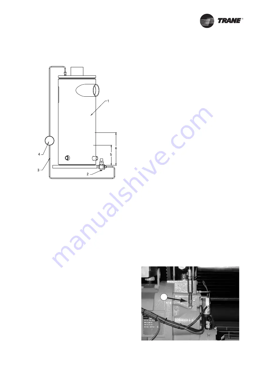
Figure 24 – Oil system schematic: Oil level measurement.
1 = Oil separator
2 = Valve
3 = 1/4” refrigeration hose
4 = Sight glass
5 = Minimum oil level
6 = Maximum oil level
How to measure the
oil level:
1.
Use the oil drain valve on the oil line and the
service valve on the oil separator (bottom side). This
measurement can be made, when the circuit is not
running. Note: the bottom plate of the oil separator is
approximately 25mm thick.
2. The initial oil charge should be approximately at the
level in of the above chart. This is the approximate
oil level if all the oil is in the oil lines, fi lter, and oil
sump, and the unit is in vacuum so that there is no
refrigerant dissolved in the oil.
3. After the unit has run for a while, the oil level in the
sump can vary greatly. However, if the unit has run at
“normal” conditions for a long time, the level should
resemble the level in the above chart: 25mm to
101mm is acceptable.
The fi eld charging procedure depends on the
circumstances that resulted in the need for oil charge.
1.
Some services procedures may result in loss of
small quantities of oil that must be replaced (oil
analysis, compressor fi lter replacement, re-tubing
the evaporator, and so forth).
2. Additionally, some maintenance procedures
may result in virtually all the oil being removed
(compressor motor burn or total removal of the
charge to trouble shoot a unit).
3. Finally, leaks may result in a loss of oil that must be
replaced.
Prelubrication
Prior to the oil charging procedure, a small amount of oil
shall be injected in the port labeled “1” on Figure 26 Oil
pushed into this location drains into the discharge port,
which allows the oil to effectively cover the rotor end
faces and rotor tips.
The only issue is that if the schraeder is not present
on this port, the 7/16 o-ring boss plug normally in this
location will have to be replaced by a 7/16-schraeder
fi tting (Trane part number VAL07306).
If this part is not available quickly, schraeder fi tting 2 or
3 (Figure 26) could be removed and put in location 1. The
plug would then replace the removed schraeder fi tting.
1.
Add 7/16 schraeder port where plug is today
(Figure 26).
2. Pull compressor and unit into Vacuum.
3. Connect oil line to port (Figure 25).
4. Let vacuum draw in ½ litre of oil.
Option: pump in ½ litre of oil. In any case, never
complete the entire oil charge by this port. This could
lead to drastic damages for the compressor. Oil injected
should be preheated.
5. Remove the oil line.
Figure 25
1
Содержание RTAF HE Series
Страница 3: ...RLC SVX19A E4 3...
Страница 36: ...RLC SVX19A E4 36 General Electrical Recommendations Figure 19 Warning Label...
Страница 59: ...RLC SVX19A E4 59 Notes...


