LPC-SVX01C-EN
53
Operation
general
information
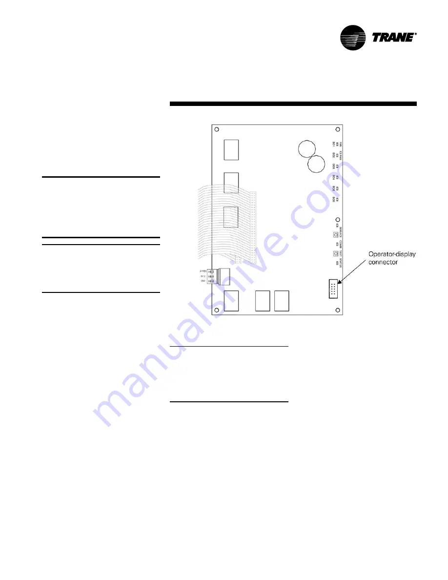
Figure O-GI-13. Operator-display connector on the Tracer AH540/541
Connecting the portable
operator display
The portable operator display is designed
for temporary connections to Tracer
AH541 controllers. It can be hot swapped.
CAUTION
Avoid Equipment Damage!
To clean the operator display, use a
cloth dampened with commercial
liquid glass cleaner. Spraying water or
cleansers directly on the screen may
result in equipment damage.
IMPORTANT: The portable operator
display is not used for time clock schedul-
ing. To provide scheduling, you must use a
permanently-connected door mounted
operator display, stand-alone operator
display, or Tracer Summit system.
To connect the portable operator display:
1. Open the Tracer AH541 enclosure
door.
2. Attach the operator-display cable to
the operator-display connector on the
circuit board (see Figure O-GI-13).
The operator display receives power
from the Tracer AH541 and turns on
automatically when it is connected to the
controller. The operator display is hot-
swappable, so there is no need to power
down the controller.
Setting up the operator display
The home screen is the starting point for
navigating through the screens of the
operator display. The home screen is
displayed when the unit is idle. The screen
contains the following information from
top to bottom:
•
Time and date
•
The controller location label: When no
location is specified and the controller
is a Tracer AH540, “Tracer AH540” is
displayed. When no location is specified
and the controller is a Tracer AH541,
“Warning: Unit Config Required” is
displayed.
•
Operating parameters of the controller
•
Push buttons: Touch one of the five
buttons — View, Alarm, Schedule,
Override, or Setup — to access the
desired set of screens.
Note: The schedule button does not
appear on the Home screen when a
portable operator display is connected to
the controller because the portable
operator display does not have a time
clock and therefore cannot be used to set
up schedules.
Setting up time and date
To change the time for the operator
display:
1.
On the home screen, press the Setup
button. The Setup menu appears.
2.
Press the down arrow button to go to
Page 2 of 2.
3.
Press the Change Time button to view
the next screen.
4.
Using the buttons, type the time using
the format hh:mm, where
hh is the
hour and
mm is the minute. Press
either the AM or PM button, as
appropriate.
5.
To correct an error, press clear and
start again. To accept the changes,
press the OK button.
To change the date for the operator
display:
1.
On the home screen, press the Setup
button. The Setup menu appears.
2.
Press the down arrow button to go to
page 2 of 2.
3.
Press the Change Date button to
view the next screen.
4.
Press the forward and back arrows to
move the cursor from day to month
to year. Use the buttons to type the
appropriate date.
5.
To correct an error, press the reset
button. To accept the changes, press
the OK button.
Calibrating the operator display
To calibrate the operator display:
1.
On the home screen, press the Setup
button. The Setup menu appears.
2.
Press the page down button to go to
Page 2 of 2.
3.
Press the Display Setup button. The
Display Setup menu appears.
4.
Press the Calibrate Touch Screen
button. A screen with a target
appears.
Содержание LPC
Страница 50: ...50 LPC SVX01C EN Operation general information Figure O GI 9 Tracer AH540 termination board ...
Страница 89: ...LPC SVX01C EN 89 Operation sequence of operation Table O SO 19 Comm LED yellow Table O SO 20 Required inputs ...
Страница 91: ...LPC SVX01C EN 91 Maintenance diagnostics Table M D 2 Tracer AH540 541 diagnostics ...
Страница 92: ...92 LPC SVX01C EN Maintenance diagnostics Table M D 2 continued Tracer AH540 541 diagnostics ...
Страница 94: ...94 LPC SVX01C EN Maintenance troubleshooting Table M T 2 Valves stay open ...
Страница 95: ...LPC SVX01C EN 95 Maintenance troubleshooting Table M T 3 Valves stay closed ...
Страница 96: ...96 LPC SVX01C EN Maintenance troubleshooting Table M T 4 Outdoor air damper stays open ...
Страница 97: ...LPC SVX01C EN 97 Maintenance troubleshooting Table M T 5 Outdoor air damper stays closed ...
Страница 98: ...98 LPC SVX01C EN Maintenance troubleshooting Table M T 6 DX cooling binary outputs do not energize ...
Страница 99: ...LPC SVX01C EN 99 Maintenance troubleshooting Table M T 7 Electric heat binary outputs do not energize ...
Страница 104: ...104 LPC SVX01C EN Maintenance appendix Figure M A 1 Flowchart EnteringWaterTemperature Sampling Function ...
Страница 107: ...LPC SVX01C EN 107 Maintenance appendix Table M A 6 Hard wired CO2 sensor values ...
Страница 109: ......


