background image

78

 OAU-SVX006E-EN

Attention Startup or Service Technician

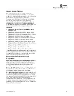
Horizon UC600 v11.0 Released

The programming has gone through an overhaul. Take a 
moment to read through the Sequence of Operation 
included in this packet to familiarize yourself with the new 
operation.

Note:

Program v11.0 is not backwards compatible with 
previous Horizon units. The point configuration has 
changed, and suction pressure transducers are 
required for proper operation. 

In the future, a package will be made available 
that’s backwards compatible with units 
manufactured after Jan 1st, 2019.

Documents Included in This Packet:

1. Sequence of Operation – Full Horizon sequence, not 

unit-specific.

2. New Startup Form

3. Unit-Specific Points List – Points not relevant to the unit 

have been removed from this document.

Unchanged from Previous Versions:

All programming and points built in. UC600 
determines sequence based on configurable points 
and what points are Out of Service (mostly Analog and 
Binary Inputs/Outputs).

Verifying setpoints with the customer is 
recommended.

Summary of Improvements

Suction Pressure Monitoring

All units with compressors will come standard with a 
refrigeration suction pressure transducer on circuit one. 
Units with digital scroll on the second circuit will also have 
a transducer on the second circuit.

Suction pressure will be used during cooling and 
dehumidification to limit capacity to prevent frost on the 
evaporator. An informational diagnostic will be displayed 
if this occurs repeatedly.

Compressor Run Status and Diagnostics

Each compressor will now have a run status by using the 
compressor auxiliary contactor. A diagnostic will be 
displayed if there is a call for a compressor with no status.

Updated Point Names to Match Tracer SC

Where possible, all points will be updated so that they 
match with standard Tracer SC key names.

Evaporator Leaving Temperature Setpoint 
Reset

Single Zone VAV and Space Control units: During

dehumidification mode the unit will reset the evaporator 
setpoint by comparing the space conditions to the 
setpoints. Previously a fixed setpoint for the evaporator 
temperature was used during dehumidification.

Minimum Supply Air Flow Setpoints

VAV units will now have separate minimum air flows 
during heating or cooling operation. Previously, the 
setting used was the highest value for all modes of 
operation. If these values are lower than a minimum 
outdoor air flow setpoint, then the outdoor air setpoint is 
used.

Single Zone VAV Mod. Air Flow - Heating 
Mode 

Single Zone VAV will now modulate supply air flow to 
maintain space temperature. Previously it was constant 
volume during heating mode.

Gas Heater Staging Off at Minimum 
Capacity

The first stage of gas heat will now stage off if the heat 
capacity is at minimum. Previously, the first stage of heat 
was locked on whenever the unit was in heating mode. 2- 
minute delays have been added to prevent short cycling.

Reduced Hot Gas Reheat Purge Mode

Previously, if the hot gas reheat was above 0% for 30 
minutes, it entered a 3-minute purge cycle at 100% signal. 
Now, if the hot gas reheat is between 10% and 50% for 30 
minutes, it will enter a 2-minute purge cycle. First half is at 
80% signal, second half is at 10% signal.

Unit Shutdown Due to Condensate 
Overflow

If the condensate overflow switch signals an alarm, and 
the unit is far from meeting setpoint, the unit is shut down 
and a diagnostic is displayed. Condensate switch required.

Liquid Line Pressure Setpoint Reset

For maximum efficiency, the liquid line pressure setpoint 
defaults to 325PSI during regular cooling mode. During 
dehumidification it resets to 450PSI for maximum reheat 
capacity in all conditions. Head Pressure Control is 
required.

Modulating ERV Exhaust and Outdoor Air 
Bypass 

All units with an Energy Recovery Wheel (ERV) will now 
have modulating bypass for both the outdoor (OA) and 
exhaust air (EA). Modulating OA bypass is used to prevent 
frosting of the ERV. Modulating EA bypass operates with 
the primary heater and is used to prevent overheating on 
mild days.

Содержание Horizon OADG Series

Страница 1: ...t l entretien de cet quipement doivent tre assur s exclusivement par du personnel qualifi L installation la mise en service et l entretien d quipements de chauffage de ventilation et de climatisation...

Страница 2: ...onsible Refrigerant Practices Trane believes that responsible refrigerant practices are important to the environment our customers and the air conditioning industry All technicians who handle refriger...

Страница 3: ...munir d ventuels risques lectriques m caniques et chimiques les techniciens DOIVENT respecter les consignes pr conis es dans le pr sent manuel sur les tiquettes et les autocollants ainsi que les instr...

Страница 4: ...on dans le circuit Consultez la plaque constructeur de l unit pour conna tre le type de fluide frigorig ne employ Utilisez uniquement des fluides frigorig nes substituts et additifs agr s WARNING Haza...

Страница 5: ...ds in open containers in the vicinity of this appliance is hazardous AVERTISSEMENT Risque d explosion et gaz mortels Le non respect de toutes les consignes de s curit ci dessous peut entra ner la mort...

Страница 6: ...Measures 14 Storage 14 Unit Clearances 15 Unit Clearances Curb Dimensions and Dimen sional Data 16 OAD Units 16 Unit Clearances 16 Curb Dimensions 17 Dimensional Data 18 OAN Units 21 Unit Clearances...

Страница 7: ...ting ERV Exhaust and Outdoor Air By pass 78 Space Control or Single Zone VAV and OA Setpoints 79 Discharge Air Temp Reset for Single Zone VAV 79 Supply Fan Tracking for Exhaust Fan Field Enabled 79 Ho...

Страница 8: ...Energy Wheel With VFD 84 Additional Features 84 Electric Pre Heat 84 Space Thumbwheel Input 84 Split Exhaust and Return Air Path 84 Outdoor Airflow Monitoring 85 Optional Field Enabled Features 85 De...

Страница 9: ...75 60 3 Digit 10 Not Used Digit 11 Indoor Coil Type 0 No Indoor Coil C DX 4 Row D DX 6 Row F Glycol Chilled Water Coil 4 Row G Glycol Chilled Water Coil 6 Row H Glycol Chilled Water Coil with Cooney F...

Страница 10: ...00 rpm C 1 5 hp 1800 rpm D 1 5 hp 3600 rpm E 2 hp 1800 rpm F 2 hp 3600 rpm G 3 hp 1800 rpm H 3 hp 3600 rpm J 5 hp 1800 rpm K 5 hp 3600 rpm L 7 5 hp 1800 rpm M 7 5 hp 3600 rpm N 10 hp 1800 rpm P 10 hp...

Страница 11: ...er Fan Options 0 No Condenser Fans A Standard Condenser Fan B Passive Head Pressure Control C Active Head Pressure Control D ECM Condenser Fans with Active Head Pressure Control E ECM Condenser Fans w...

Страница 12: ...the Main Control Panel The Main Unit Display and RTRM receive information from sensors and customer binary contacts to satisfy the applicable request for ventilation cooling dehumidification and heati...

Страница 13: ...odulating high turndown indirect fired gas heat The heating section will include high turn down burners and a stainless steel tubular heat exchanger The heat exchanger will be constructed of type 439...

Страница 14: ...nal components for shipping damage as soon as possible after delivery and before it is stored Do not walk on the sheet metal base pans Ifconcealed damage is discovered notify thecarrier s terminal of...

Страница 15: ...and service clearances for either a single or multiple unit installation These clearances are the minimum distances necessary to assure adequate serviceability cataloged unit capacity and peak operati...

Страница 16: ...pouvant r sulter en des blessures corporelles graves voire mortelles ou des dommages mat riels Reportez vous la plaque signal tique de l unit et aux instructions d installation pour conna tre les dis...

Страница 17: ...3 24 5 62 2 1 75 4 4 TOP FLANGE Figure 6 Unit curb data for OAD cabinet with powered exhaust but no ERV in cm 56 142 2 18 45 7 1 75 4 4 TOP FLANGE 138 875 352 7 26 66 0 5 12 7 5 12 7 13 75 34 9 13 33...

Страница 18: ...UCT FLANGE 36 451 92 6 110 437 280 5 146 888 373 1 8 063 20 5 7 094 18 68 594 174 2 29 000 73 7 110 000 279 4 GAS HEAT ONLY 5 250 13 3 5 250 13 3 13 000 33 VR 46 000 116 8 VR 8 500 21 6 52 500 133 4 V...

Страница 19: ...1 92 6 146 000 370 8 8 063 20 5 38 845 98 7 68 594 174 2 6 250 15 9 23 500 59 7 HS 23 500 59 7 HS 29 000 73 7 61 750 156 8 27 500 69 9 HR 19 500 49 5 HR Unit Clearances Curb Dimensions and Dimensional...

Страница 20: ...HAUST 52 500 133 4 VS 26 500 67 3 VS 10 000 25 4 BE 65 000 165 1 46 000 116 8 VR 5 250 13 3 28 000 71 1 34 500 87 6 5 250 13 3 16 071 40 8 46 000 116 8 BE 10 000 25 4 VR 15 500 39 4 HR 31 500 80 0 HR...

Страница 21: ...h ERV in cm 36 0 91 4 36 0 91 4 96 0 243 8 54 0 137 2 Note 72 in 182 9 cm clearance is required above the condenser fans Figure 14 Unit to unit clearance in cm 84 000 213 36 96 000 243 84 Curb Dimensi...

Страница 22: ...194 23 4 10 514 26 7 107 518 273 1 2 000 5 1 HS HR DUCT FLANGE TYPICAL 109 194 277 4 OPTIONAL BAROMETRIC RELIEF DAMPER 60 000 152 4 HR 24 500 62 2 HR 32 750 83 2 5 250 13 3 7 500 19 1 51 000 129 5 HS...

Страница 23: ...500 16 5 33 959 86 3 46 000 116 8 43 000 109 2 VS 20 000 50 8 VR 10 750 27 3 10 750 27 3 10 750 27 3 10 750 27 3 73 500 186 7 VS 11 000 27 9 VE 76 154 193 4 76 500 194 3 VE 76 500 194 3 VR 10 500 26 7...

Страница 24: ...11 000 27 9 VE 76 500 194 3 VE 102 000 259 1 10 500 26 7 10 750 27 3 10 750 27 3 10 750 27 3 10 750 27 3 19 000 48 3 98 000 248 9 9 194 23 4 10 514 26 7 107 518 273 1 2 000 5 1 HS HR DUCT FLANGE TYPI...

Страница 25: ...hnician which could result in death or serious injury and equipment or property only damage Test lift unit approximately 24 inches to verify proper center of gravity lift point To avoid dropping of un...

Страница 26: ...5 27 28 20 a Refer to Figure 21 p 26 and Figure 22 p 26 for corner locations Table 3 Typical unit weight center of gravity and corner weights percentage of total weight air cooled units with powered e...

Страница 27: ...SPREADER BARS A SCALE 1 12 DETAIL A SCREW PIN SHACKLE 4 LOCATIONS SPREADER BARS A DETAIL A SCALE 1 14 SCREW PIN SHACKLE 4 LOCATIONS Figure 26 Six point lift OAD cabinet with ERV section Figure 27 Eig...

Страница 28: ...ween the lifting hook and the top of the unit should be 7 feet 3 Test lift the unit to ensure it is properly rigged and balanced make any necessary rigging adjustments 4 Lift the unit and position it...

Страница 29: ...hnicians in order to protect themselves from potential electrical mechanical and chemical hazards MUST follow precautions in this manual and on the tags stickers and labels as well as the following in...

Страница 30: ...in Figure 32 Pitch drain lines connected to P Trap at least 1 2 inch for every 10 feet of horizontal run to assure proper condensate flow Do not allow the horizontal run to sag causing a possible dou...

Страница 31: ...primed and of adequate height to allow for cabinet operating negative pressure Figure 33 OAD water inlet and outlet in cm Water inlet Water outlet 2 865 7 3 15 943 40 5 18 807 47 8 31 055 78 9 0 890 2...

Страница 32: ...3 8 OAD 6 row 2 0 5 1 OAN 4 row 2 5 6 3 OAN 6 row 3 0 7 6 WARNING Proper Field Wiring and Grounding Required Failure to follow code could result in death or serious injury All field wiring MUST be pe...

Страница 33: ...Figure 38 OAD utility connections in cm Electric Disconnect Gas Inlet 1 5 in NPT 3 8 cm Condensate Drain 1 in NPT 2 5 cm 27 000 68 6 22 446 57 0 7 500 19 1 49 446 125 6 8 500 21 6 15 000 38 1 69 250...

Страница 34: ...are not designed to accept other types of conductors WARNING Proper Field Wiring and Grounding Required Failure to follow code could result in death or serious injury All field wiring MUST be perform...

Страница 35: ...ectrical Components Failure to follow all electrical safety precautions when exposed to live electrical components could result in death or serious injury When necessary to work with live electrical c...

Страница 36: ...hts on the face of the sequencer The ABC indicator light will glow if the phase is ABC If the CBA indicator light glows turn main source power off and then open the unit main disconnect device cover a...

Страница 37: ...ne peut entra ner des blessures graves voire mortelles Avant toute intervention coupez l alimentation lectrique y compris aux sectionneurs distance Suivez scrupuleusement les proc dures de verrouillag...

Страница 38: ...ace Refer to Figure 50 p 77 for installation instructions If modulating OA RA dampers w economizer and an exhaust fan are selected a duct static pressure sensor VELCON 0350 will be factory provided fo...

Страница 39: ...ring installed and landed 5 Accessories installed 6 Ductwork installed all runs in place final tie in complete 7 Drain lines installed and properly terminated 8 Startup appointment with Horizon certif...

Страница 40: ...ption AI 01 Space Temperature Local 40 95 F Hardwired input from field installed space temperature sensor wired to OAUTS 1 2 SPTC AI 02 Space Humidity Local 0 100 Hardwired input from field installed...

Страница 41: ...energy recovery wheel and the indoor coil ERSTC AI 18 Liquid Line Refrigerant Pressure Circuit 1 Local 0 500 psi Hardwired input from factory installed pressure transducer on the refrigeration circuit...

Страница 42: ...second stage AO 13 Energy Recovery Exhaust Air Bypass Position Command 0 100 Analog output for modulating ERV exhaust air bypass AV 01 Occupied Cooling Setpoint 72 F 55 85 F Space cooling setpoint us...

Страница 43: ...ied Dewpoint Enable Setpoint 65 F 49 100 F If the space dewpoint rises above this setpoint during unoccupied mode then dehumidification will be enabled AV 29 Outdoor Air Cooling Enable Setpoint 45 100...

Страница 44: ...ure AV 55 Direct Fired Profile Width 6 28 Width of the profile opening for direct fired heaters Used to calculate air flow AV 56 Return Duct Space Pressure Setpoint 0 5 1 3 in H2O Setpoint used for ex...

Страница 45: ...a differential pressure switch BI 02 Emergency Stop 0 Normal 1 ESTOP Auto Reset Shuts the unit down BI 03 Final Filter Status 0 Clean 1 Clogged Auto Reset Notificaiton when differential presssure swi...

Страница 46: ...f Feedback run status hardwired through compressor contactor BI 21 Compressor 5 Status 0 On 1 Off Feedback run status hardwired through compressor contactor BI 22 Compressor 6 Status 0 On 1 Off Feedba...

Страница 47: ...0 Off 1 On Defrost status for outdoor coil BV 05 Hot Gas Reheat Purge Mode 0 Off 1 On Purge status for hot gas reheat BV 07 Auxiliary Heating Mode 0 Allowed 1 Not Allowed Used to interlock primary he...

Страница 48: ...on the circuit 1 refrigeration BV 64 Compressor Low Ambient Lockout Active 0 Active 1 Not Active Status indicating that the unit is calling for cooling but the compressors are locked out due to low am...

Страница 49: ...ee Cooling Mode 4 Ventilation Mode MV 19 Compressor 1 Status Active 1 Disabled 2 Enabled No Running Status 3 Enabled With Running Status 4 Enabled No VFD Alarm 5 Not Installed MV 20 Compressor 2 Statu...

Страница 50: ...figure viii Make calibration offset the opposite of the number listed as supply fan pressure ix For example if the supply fan pressure is listed as 0 18 set the calibration offset to 0 18 and save x R...

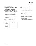
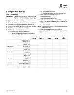
Страница 51: ...SVX006E EN 51 b Override Circuit 1 to 0 c Override HGRH to 100 d Maintain head pressure 400 psi e Record electrical data refrigerant pressures saturated temps and line temps on Horizon Start Up sheet...

Страница 52: ...ssures graves voire mortelles Les techniciens afin d tre prot g s des ventuels risques lectriques m caniques et chimiques DOIVENT suivre les pr cautions contenues dans ce manuel sur les tiquettes et l...

Страница 53: ...tion Verify Indoor Fan Failure Switch OAB or OAG cabinets with UC600 controls a TheminimumofAnalogValueslabelledSupplyFan AirFlowMinimumSetpointisCoolingMode AV59 and Supply Fan Air Flow Minimum Setpo...

Страница 54: ...ould be 1 2 in WC during the warm up period The manifold pressure will rise to 3 5 in WC at 100 percent firing rate Following these sequences to check low fire gas pressure for modulating section redu...

Страница 55: ...r yellow tipping of natural gas flame or a long yellow flame on propane may be caused by lint and dirt accumulation inside burner or at burner ports at air inlet between burner and manifold pipe or de...

Страница 56: ...l be read thru the meter s COM and A connections The meter should read greater than 1 0 A Note If the meter reads below 0 on scale meter leads are reversed disconnect power and reconnect meter leads f...

Страница 57: ...erature rise and shut off gas supply through the ignition control module Flame rollout can be caused by insufficient airflow for the burner firing rate high gas pressure blockage of the vent system or...

Страница 58: ...he bearings as necessary Verify that all wire terminal connections are tight Remove any corrosion present on the exterior surfaces of the unit and repaint these areas Generally inspect the unit for un...

Страница 59: ...or serious injury Coil cleaning agents can be either acidic or highly alkaline and can burn severely if contact with skin occurs Handle chemical carefully and avoid contact with skin ALWAYS wear Pers...

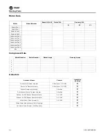
Страница 60: ...____________________________ _____________________________________________________ _____________________________________________________ _____________________________________________________ connectio...

Страница 61: ...ft2 m2 10 0 93 10 0 93 10 0 93 17 1 58 17 1 58 Rows 6 or 4 6 or 4 6 or 4 6 or 4 6 or 4 FPI 14 or 15 14 or 15 14 or 15 14 or 15 14 or 15 Refrigerant Control TXV TXV TXV TXV TXV Drain Connection Number...

Страница 62: ...4 14 14 14 Refrigerant Control TXV TXV TXV TXV TXV Drain Connection Number 1 1 1 1 1 Drain Connection Size in mm 1 25 4 1 25 4 1 25 4 1 25 4 1 25 4 Outdoor Fan Type Propeller Propeller Propeller Prope...

Страница 63: ...12 7 1 2 12 7 1 2 12 7 1 2 12 7 1 2 12 7 1 2 12 7 Tube Size 4 row OD in mm 3 8 9 5 3 8 9 5 3 8 9 5 3 8 9 5 3 8 9 5 3 8 9 5 3 8 9 5 Face Area 6 row ft2 m2 26 2 42 26 2 42 26 2 42 34 3 16 34 3 16 34 3...

Страница 64: ...17 500 14 866 29 733 10 000 20 000 16 990 33 980 Compressor Number 4 4 4 4 4 4 5 Type Scroll Scroll Scroll Scroll Scroll Scroll Scroll Outdoor Coil Type High Performance High Performance High Perform...

Страница 65: ...1750 3500 Motor Frame Size Standard Oversized Varies Varies Varies Varies Varies Varies Varies Filters Type Furnished Refer to OAU Filter Guide in Appendix p 73 Refer to OAU Filter Guide in Appendix p...

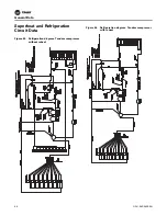
Страница 66: ...General Data 66 OAU SVX006E EN Superheat and Refrigeration Circuit Data Figure 43 Refrigeration diagram Tandem compressor without reheat Figure 44 Refrigeration diagram Tandem compressor with reheat...

Страница 67: ...General Data OAU SVX006E EN 67 Figure 45 Refrigeration diagram ASHP Tandem compressor without reheat Figure 46 Refrigeration diagram ASHP Tandem compressor with reheat...

Страница 68: ...Alarm icon on the display will register ALARM illuminate red and flash Important The space temperature sensor SPTC and space relative humidity sensor SPHC will read failed if they are not connected t...

Страница 69: ...Diagnostic Fire Shutdown Auto Reset Diagnostic from BAS communication Unit resets once this returns to normal BAS only BV 10 Diagnostic Low Discharge Air Temp Lockout Manual Reset Occurs when the disc...

Страница 70: ...or less than the minimum BV 31 Diagnostic Liquid Line Refrigerant Pressure Circuit 1 Source Failure Auto Reset Occurs when circuit 1 is running and the liquid line transducer is outside of the 150 65...

Страница 71: ...al or Auto Reset Occurs when there is a call for a compressor without a run status for five minutes Auto resets after three hours BV 53 Diagnostic Compressor 3 Run Failure Manual or Auto Reset Occurs...

Страница 72: ...who has been properly trained in handling live electrical components perform these tasks AVERTISSEMENT Composants lectriques sous tension Le non respect de toutes les consignes de s curit lors de la...

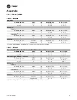
Страница 73: ...eheat is provided Table 17 OAN units Evaporator 40 to 50 ton 4 and 6 row coils 55 to 100 ton 6 row coils Thickness in cm MERV Qty Height in cm Width in cm 2 5 1 8 13 15 20 50 8 18 45 7 4 10 2 14 15 20...

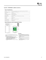
Страница 74: ...Appendix 74 OAU SVX006E EN Field Installation of Factory Provided Sensors Figure 47 VELSEN 0021 installation instructions...

Страница 75: ...Appendix OAU SVX006E EN 75 Figure 48 BAYSENS036A installation instructions...

Страница 76: ...Appendix 76 OAU SVX006E EN Figure 49 Supply duct static pressure transducer SDPC ON 1 2 3 R1 R5 R3 R2 R4 O1 O5 O3 O2 O4 OFF...

Страница 77: ...Appendix OAU SVX006E EN 77 Figure 50 Return duct space pressure transducer RDSPC ON 1 2 3 R1 R5 R3 R2 R4 O1 O5 O3 O2 O4 OFF...

Страница 78: ...ontrol units During dehumidification mode the unit will reset the evaporator setpoint by comparing the space conditions to the setpoints Previously a fixed setpoint for the evaporator temperature was...

Страница 79: ...displayed for the sensor when another sensor is being used Evaporator temperature sensor fail use suction pressure Supply duct static pressure sensor fail use constant volume at minimum air flow Spac...

Страница 80: ...heating setpoints Dehumidification Temperature Setpoint Active is controlled by Dehumidification Temperature Setpoint Occupied Control Starting Sequence Occupied operation begins when the unit is pla...

Страница 81: ...ntilation Mode heating and cooling is locked out and the unit supplies un conditioned air Ventilation Mode is locked out whenever the unit is in Dehumidification Mode Multi Zone VAV Control Ventilatio...

Страница 82: ...ded as Heat Pump Fail Switch Point Heat pump operation is re attempted when the temperature rises by 5 F The unit switches Auxiliary Heating Mode to Allowed when the Outdoor Air Temperature Active fal...

Страница 83: ...Dehumidification Mode Cooling Capacity is adjusted to maintain the Dehumidification Temperature Setpoint Active which is written to by Dehumidification Temperature Setpoint adjustable Hot Gas Reheat...

Страница 84: ...ctive for variable effectiveness capacity control Once the bypass damper becomes fully closed the primary heater will be engaged Energy Wheel Without VFD The unit prevents frost accumulation on the ER...

Страница 85: ...onditions as described under the occupied section the Outdoor Air Damper Position Command will open to the Outdoor Air Damper Maximum Position Setpoint No Return Air Damper Installed Identical to occu...

Страница 86: ...d The unit is shut down when this diagnostic occurs including the supply fan Diagnostic High Low DischargeAirTempLockout is displayed when the Discharge Air Temperature Local is above 128 F below35 F...

Страница 87: ...re Source Failure Diagnostic Space CO2 Source Failure Diagnostic Space Humidity Source Failure Diagnostic Space Temperature Source Failure The Dehumidification Temperature Sensor is the Indoor Coil Le...

Страница 88: ...it Tag Technician Name Horizon Tech Training Completed Yes No Date Completed Startup Date Checked for visible shipping damage Unit is level All fans spin freely All electrical connections tight Interi...

Страница 89: ...ckwise IFFR relay should then be lit 6 Release Supply Fan Speed Command Rated Voltage Measured Voltage L1 L2 Voltage L1 L3 Voltage L2 L3 Voltage L1 G Voltage L2 G Voltage L3 G TNS2 Secondary Voltage V...

Страница 90: ...r Serial Number Rated Amps Running Amps 1 2 3 4 5 6 Actuator Name Control Operation Verified Outdoor Air Damper Actuator 2 Position or 2 10 VDC Return Air Damper Actuator 2 Position or 2 10 VDC Exhaus...

Страница 91: ...er flow through water coil 7 Adjust charge until subcooling is 10 15 8 Record all readings 9 Verify HGRH operational at 100 10 Heat Pumps Switch reversing valve to heating repeat steps 1 8 for heating...

Страница 92: ...urnace 2 Furnace 3 Measured Pressure Natural Gas Settings Propane Settings Incoming to Unit 7 14 11 14 in H2O Between On Off Mod Valve 5 10 5 in H2O Stage 1 Manifold Low Fire 0 4 1 2 in H2O Stage 1 Ma...

Страница 93: ...rts at the top left Point Summary Report and then Generate Report on the popup window None of the checkboxes need to be checked Commissioning Do not attempt to perform commissioning by putting points...

Страница 94: ...ed space temperature setpoint overwrites Occupied Cooling and Heating Setpoints Factory defaulted Out of Service put In Service to use MULTI ZONE VAV AV 10 Outdoor Air Dewpoint Enable Setpoint 55 45 1...

Страница 95: ...here something missing or do you have recommendations on improvements Note here if the outdoor air temperature is too low for cooling testing Submit completed form to horizonstartup kccmfg com Include...

Страница 96: ...are committed to using environmentally conscious print practices Trane by Trane Technologies NYSE TT a global climate innovator creates comfortable energy efficient indoor environments for commercial...

Отзывы: