Subject to technical modification
Smarty 3X P_P0094_AZ_0002
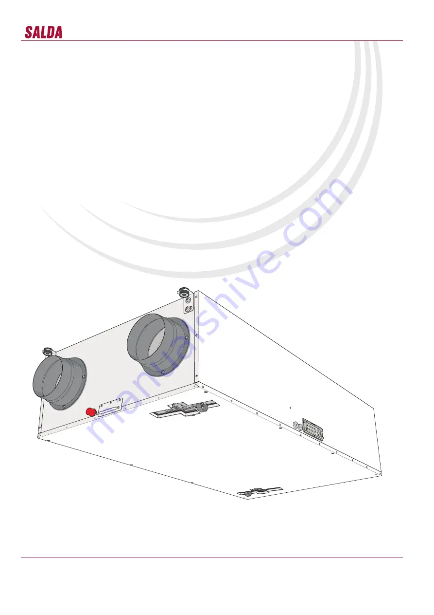
AHU WITH HEAT RECOVERY
Smarty 3X P
User and service technical manual
Страница 1: ...Subject to technical modification Smarty 3X P_P0094_AZ_0002 AHU WITH HEAT RECOVERY Smarty 3X P User and service technical manual...
Страница 2: ...ndow 23 Ptouch mode setting window 23 Ptouch menu 24 Ptouch state 24 Ptouch menu set points window 25 Ptouch date and time setting 25 Ptouch weekly schedule 26 Ptouch holiday schedule 26 Ptouch air fi...
Страница 3: ...3025238 IV PV KE PE M 0 084 kW 0 92 A 230 50 V Hz 1 0 085 kW 0 93 A 230 50 V Hz 1 kW A 0 V Hz 0 kW A 0 V Hz 0 0 005 kW 0 021 A 24 50 V Hz 0 17 kW 1 87 A IP 34 TOTAL gu072489 2014 03 www salda lt 1 3 4...
Страница 4: ...x 195 x 25 mm Operating ambient temperatures 5 40 C Unsuitable for operation in pools saunas and other similar premises All units are packed in the factory to withstand regular conditions of transport...
Страница 5: ...ly That can be performed only by qualified electrician Do not use water or another liquid to clean electrical parts or connections If you notice condensat on electrical parts or connections stop opera...
Страница 6: ...n the heat exchanger once a year Firstly take out heat exchanger cassette carefully Submerge it into a bath and wash with warm soapy water do not use soda Then rinse it with weak hot water stream too...
Страница 7: ...lead to accelerated wear on motor bearings and noise vibration Clean impeller and inner housing with mild detergent water and damp soft cloth Do not use high pressure cleaner abrasives sharp instrumen...
Страница 8: ...lient determines that equipment is found to be faulty or a breakdown occurred he should inform the manufacturer within five working days and deliver the equipment to manufacturer Delivery costs should...
Страница 9: ...9 Smarty 3X P www salda lt Mounting on the wall with condensate tube downwards Any slopes are necessary 1 0 o 1 0o 826 Ceiling mounting with the cover downwards The slope towards the tube 0 5 1o 826...
Страница 10: ...The start up and operation of the unearthed ventilation unit is prohibited It is prohibited to use extension wires cables and power network plug socket distribution devices Prior to carrying out any...
Страница 11: ...75 speed min 1 3200 protection class IP 34 Thermal efficiency up to 94 Total power consumption power current kW A 0 168 1 5 Insulation of walls mm 15 30 Color RAL white 9016 Weight net without packing...
Страница 12: ...sor PIR Motion detector DJ Smoke detector TJ Supply air temperature sensor CEE7 7 Power cable with plug X19 BMS network connection place X18 Control panel connection place PC Personal computer MBGatew...
Страница 13: ...CO2 CO2 sensor ZAKKT0049 AKS 160 9 Silencer GSOAKS006 Stouch Remote control panel PRGPU51 Levelling feet GAGKSMARTY168_1000 Smarty 3X P legs S KFF U Dust RH sensor ZAKKT0051 Humidity RH sensor ZAKKT00...
Страница 14: ...1 By default temperature is not controlled but under request it is possible to specify the desired temperature economy the mode is intended to save energy when there are no people in the premises In t...
Страница 15: ...e the current mode manu ally System will inform about the next change of the mode under the schedule If any of the above mentioned functions has changed it s state into Stand by mode system checks if...
Страница 16: ...g results etc Event description and time is saved in the history Filter timer setting Air filter timer informs the user about time to change the filters After changing the filters timer should be rese...
Страница 17: ...oolers are used for supply air temperature and humidity reduction Water freezing temperature should be indicated for the water cooler Minimal time period between the on and off should be specified for...
Страница 18: ...ng operated directing exhaust air flow to outdoor air flow by outdoor air and calculated frost temperature The difference between calculated and specified temperature during activation is indicated El...
Страница 19: ...r failure Emergency run Warning Exhaust air temperature sensor failure Emergency run Warning Fresh air temperature sensor failure Emergency run Warning Hydraulic heater water temperature sensor failur...
Страница 20: ...of the func tion by touching B4 and B6 Maximum BOOST running time 180m 3h B4 B6 L4 L7 Review and cancel alarms For canceling press down B2 and B3 for 3 seconds In case of alarms L4 L5 L6 L7 flash and...
Страница 21: ...box temperature sensor failure Emergency run A 24 Supply air temperature sensor failure System stopped Nr Name Possible values Default value P 01 Sleep mode 0 Off 1 99 sleeping time in seconds 0 P 02...
Страница 22: ...n pressure protection System stopped A 43 Extract fan pressure protection System stopped A 44 Internal system error A 45 Heater manual protection Boosting A 46 Preheater manual protection Boosting Sim...
Страница 23: ...re B1 B2 B3 I1 B4 B5 Number Definition Number Definition I1 Current operating mode B1 STANDBY AHU is stopped B2 BUILDING PROTECTION maintain minimal air move ment Temperature can be maintained dependi...
Страница 24: ...perating mode B9 List of current faults B4 Review or modify set temperatures for all modes B10 Service menu B5 Filter maintenance status B11 Show previous menu row B6 Set AHU control unit s date and t...
Страница 25: ...mode I4 Room air temperature during comfort mode B4 On off switch for temperature maintaining function during economy mode I5 State of temperature maintaining function during build ing protection mode...
Страница 26: ...ivated on oc currence of selected event I5 Event time 24h format B5 Buttons to select active weekdays for selected event B6 Dials to set event hour and minute I1 B1 B5 I4 B5 I3 B2 I3 I2 B6 I5 B6 B4 Nu...
Страница 27: ...s remaining till filter service B1 Button to reset filter timer Use only after filter replacement and at Your own risk B1 I1 B2 I2 Number Definition Number Definition I1 Set boost period B1 Button to...
Страница 28: ...Default range Number Definition Default range I1 Function state green strip on gray off OFF B1 Function on off switch I2 Set temperature indication B2 Buttons to increase value I3 Minimum day temperat...
Страница 29: ...3 3 STEP_B X13 4 STEP_A X13 5 STEP_A X13 6 24VDC N3 MCB X4 1 DI4 X4 2 12VDC N3 MCB X5 1 AI1 NTC X5 2 GND X5 3 AI2 NTC X5 4 GND X5 5 AI3 NTC X5 6 GND X6 1 AI5 NTC X6 2 GND N3 MCB Bypass actuator Fire a...
Страница 30: ...rba vartotojas Components and cables marked with the dash line connected by SALDA or customer PE N L KE1 EKA 0 3 1F PE N L1 0 10V GND PE1 EKA NIS 1 0 1F 22 22 29 29 27 27 21 21 X3 1 DI1 X3 2 12VDC X3...
Страница 31: ...1 control GND X24 2 control 0 10VDC Note connection of the components to the unit The maximum permissible pre heater s power 1kW 230V 50Hz Power circuit at EX2 X 39 Purpose of connectors EX2 X 39 1 pr...
Страница 32: ...OFF N L1 L1 M3 Vin GND AO1 Transmitter 1 Vin GND AO1 Transmitter 2 Jumper 5 System mode switch H1 H2 Jumper 6 Fan speed switch 42 42 41 41 37 37 38 38 35 35 39 39 36 40 36 40 37 39 39 40 41 41 38 38 3...
Страница 33: ...tor M3 X35 5 Extract air actuator M3 phase DO5 opening X35 6 Extract air actuator M3 phase DO6 closing X35 7 Extract air actuator M3 neutral N 1 Actuator power supply voltage 230 V 50 Hz Extract air R...
Страница 34: ...neral GND X28 4 analog input 0 10 V DC Purpose of the connectors START EX1 X27 1 signal output max 100mA X27 2 power supply 24 V DC STOP EX1 X27 3 signal output max 100mA X27 4 power supply 24 V DC Co...
Страница 35: ...e connection scheme 1 04 2015 05 13 2015 05 13 2015 05 13 Punktyrine linija pa ym tus komponentus ir kabelius pajungia SALDA arba vartotojas Components and cables marked with the dash line connected b...
Страница 36: ...y 1f 230VAC L1 N PE X1 Power in X15 1 24VDC X15 1 24VDC X15 2 GND X15 3 PE N3 MCB 58 59 60 61 62 63 65 72 48 48 50 50 49 49 53 54 55 56 74 52 52 73 56 73 Power in Power in X46 1 L L2 X46 2 N L1 X46 3...
Страница 37: ...nas GN YE Green Yellow alias Geltonas PE N L1 10V Tach GND 0 10V in PV H4 PE N L1 10V Tach GND 0 10V in IV H4 N2 N3 N3 N3 N3 43 43 47 47 49 48 48 49 50 50 45 46 46 45 44 44 71 71 68 68 70 70 67 67 69...
Страница 38: ...duct Tool for drilling holes are required for its installation CO 2 concentration ppm 3000 Effect on an individual 2500 2000 Reduced concentration drowsi ness headache etc 1500 1000 Pettenkofer limit...
Страница 39: ...ust be thoroughly cleaned Check whether operation systems and unit elements as well as automation and automation devices were not damaged during installation all consumers are connected to power suppl...
Страница 40: ...40 Smarty 3X P www salda lt 1 LED1 indicator 2 control panel name 1 2 Supply air flow pressure sensor Extract air flow pressure sensor 1 2...
Страница 41: ...41 Smarty 3X P www salda lt 1 LED1 indicator 2 control panel name 2 1 2 1...
Страница 42: ...42 Smarty 3X P www salda lt 1 2 1 LED1 indicator 2 control panel name 3 remote controller 4 BMS 3 4 1 2...
Страница 43: ...er supply line of the electrical heater LED7 Output DO5 of the supply extract air damper control open LED8 Output DO6 of the supply extract air damper control close SL1 DIP switch Purpose ON position...
Страница 44: ...tion Fan cleaning Once a year Heat exchanger cleaning Once a year Filter replacement Every 3 4 months NOTE The purchaser is required to fill in the Product maintenance table 2 At least 2 Look at the p...